Built-in motor rolling brush mechanism and dust collector thereof

A technology of rolling brush and water outlet mechanism, which is applied in the direction of vacuum cleaners, machine parts, suction nozzles, etc., which can solve the problems of difficult sticky dirt removal, inability to deal with ground pollution, and large size of vacuum cleaner heads, so as to save equipment costs and reduce Dimensions and the effect of reducing the number of parts

Inactive Publication Date: 2018-11-06
SUZHOU IELECTRICA APPLIANCE CO LTD
View PDF9 Cites 5 Cited by
  • Summary
  • Abstract
  • Description
  • Claims
  • Application Information

AI Technical Summary

Problems solved by technology

Existing electric brushes are often driven by an external motor through gears and belts. Generally, the motor is arranged parallel to the brush roller, so the overall size of the vacuum cleaner head is large, and it is difficult to clean some corners
In addition, the existing vacuum cleaners mainly use the rotating bristles to sweep away the dust and sundries on the ground, and use negative pressure suction to collect the dust and sundries, but this still cannot cope with all the dirty conditions on the ground
The traditional family floor plot includes sweeping and mopping the floor. Mopping the floor can take away some water-soluble stains on the floor. The entire cleaning process of the traditional vacuum cleaner is carried out in a dry state, and it is difficult to remove some sticky dirt. There are limitations

Method used


Image

  • Built-in motor rolling brush mechanism and dust collector thereof
  • Built-in motor rolling brush mechanism and dust collector thereof
  • Built-in motor rolling brush mechanism and dust collector thereof

Examples


Embodiment Construction

[0026] Below in conjunction with specific embodiment, the content of the present invention is described in further detail:

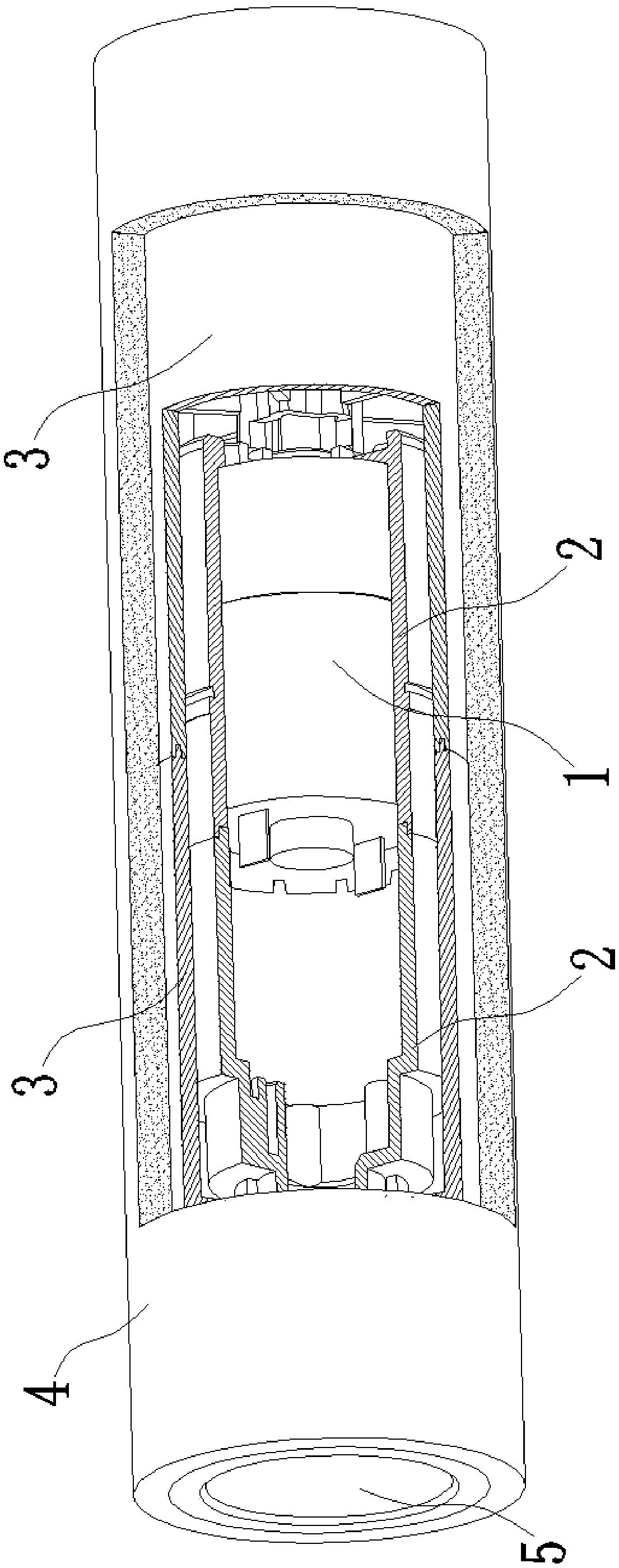
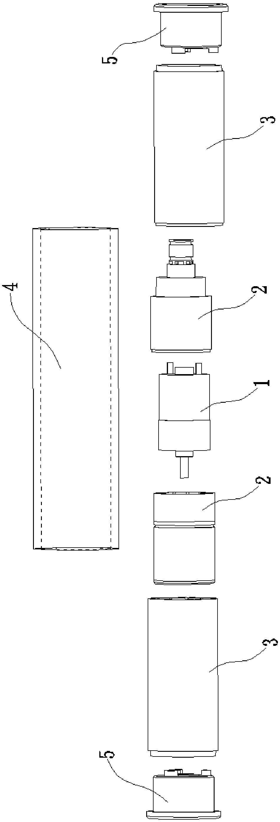
[0027] In order to achieve the purpose of the present invention, a built-in motor rolling brush mechanism includes: a motor 1, which is a rotating motor; an inner cylinder 2, which is in the shape of a hollow cylinder and wraps the motor 1; The circumferential surface is covered with a cloth 4; the water outlet mechanism wets the cloth 4; the inner cylinder 2 and the cloth cylinder 3 are coaxially arranged, and the cloth cylinder 3 is driven by the motor 1 to rotate.

[0028] figure 1 It is a three-dimensional cutaway view. The wiper 4 and the inner cylinder 2 can be glued or glued together. The wiper 4 itself is a flexible fixed non-woven fabric material. of.

[0029] The beneficial effect of adopting the above technical solution is that the motor is located inside the rag cylinder, which greatly saves space, reduces the size of the head of the vacuum...


PUM


Abstract

The invention discloses a built-in motor rolling brush mechanism and a dust collector thereof. The built-in motor rolling brush mechanism comprises a motor, an inner tube and a cleaning cloth tube, wherein the motor is a rotary motor; the inner tube with a hollow cylindrical shape covers the motor; the cleaning cloth tube is in a tubular shape; the inner tube and the cleaning cloth tube are in coaxial arrangement; the cleaning cloth tube is driven to rotate by the motor; a clean water outlet used for wetting the cleaning cloth and a suction opening for sucking away sewage on the cleaning clothtube are formed in the outer side of the cleaning cloth tube. A water controlling groove plate is also arranged between the water outlet and the cleaning cloth; the water controlling groove plate divides the flow of clean water onto the cleaning cloth. By using the built-in motor rolling brush mechanism, the motor is positioned inside the cleaning cloth tube; the dimension is reduced; the wall edges can be conveniently cleaned; the wet cleaning cloth can further improve the cleaning effect; the use of the water outlet and collecting mechanism is convenient; the work intensity of users is reduced.

Description

technical field [0001] The invention relates to the field of vacuum cleaners, in particular to a built-in motor rolling brush mechanism and a vacuum cleaner thereof. Background technique [0002] The existing vacuum cleaner styles are generally divided into two types: one is a vacuum cleaner that uses alternating current to generate negative pressure suction, and vacuums purely with the suction of a hollow tube; the other is a vacuum cleaner with an electric brush, and the bristles on the electric brush are peeled off. , Raise the dust on the surface, and then collect it. Both of these vacuum cleaners are dry dust collectors and do not involve water. The existing electric brushes are often driven by external motors through gears and belts. Generally, the motors are arranged in parallel with the brush rollers, so that the overall size of the vacuum cleaner head is large, and it is difficult to clean some corners. In addition, the existing vacuum cleaner mainly uses the rota...

Claims


Application Information

Patent Timeline
Patent Type & Authority Applications(China)
IPC IPC(8): A47L9/04A47L7/00A47L11/282A47L11/40
CPCA47L7/00A47L9/04A47L11/282A47L11/4041A47L11/4069A47L11/408
Inventor 沈会方
Owner SUZHOU IELECTRICA APPLIANCE CO LTD
Why Eureka
Try Eureka