Semi-automatic groove cutting machine

A semi-automatic, cutting machine technology, applied in welding equipment, gas flame welding equipment, metal processing equipment, etc., can solve problems affecting product quality and enterprise production efficiency, waste of human resources, waste of time, etc., to reduce labor costs, easy to Control and improve the effect of enterprise efficiency

Pending Publication Date: 2018-11-06
HENAN JINJIYE HEAVY IND CO LTD
View PDF0 Cites 3 Cited by
  • Summary
  • Abstract
  • Description
  • Claims
  • Application Information

AI Technical Summary

Problems solved by technology

[0005] In order to solve the existing single sports car bevel cutting machine in use, the small sports car is a one-way cycle, and the track and angle of the small sports car are adjusted back and forth, which wastes time, increases processing errors, causes waste of human resources, reduces work efficiency, and affects For technical issues such as product quality and enterprise production efficiency, the present invention provides a semi-automatic bevel cutting machine to achieve reasonable structure, ingenious design, safe and convenient use, repeatable and uninterrupted work, avoid repeated adjustment of the position of the sports car and the workpiece, and save gas. The purpose of reducing consumption, improving work efficiency, and reducing production costs

Method used


Image

  • Semi-automatic groove cutting machine
  • Semi-automatic groove cutting machine
  • Semi-automatic groove cutting machine

Examples


Embodiment Construction

[0026] The specific implementation manners of the present invention will be further described in detail below in conjunction with the accompanying drawings.

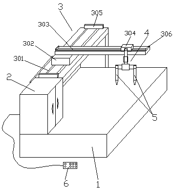
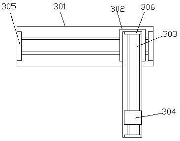
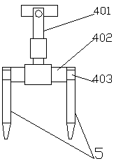
[0027] As shown in the figure, a semi-automatic bevel cutting machine includes a working platform 1, an electrical control cabinet 2, a moving mechanism 3, a lifting mechanism 4 and a double cutting torch 5, the moving mechanism 3 is located on one side of the working platform 1, and the electrical control cabinet 2 Located at the end of the moving mechanism 3, the lifting mechanism 4 is located on one side of the moving mechanism 3, and the double cutting torch 5 is fixedly arranged at the lower part of the lifting mechanism 4, and the movement of the moving mechanism 3 is controlled by the electric control cabinet 2 and drives the double cutting torch 5 on the working platform 1 For workpiece cutting, the motion mechanism 3 includes a longitudinal track 301, a longitudinal speed-regulating sports car 302, a transverse t...


PUM


Abstract

The invention relates to a semi-automatic groove cutting machine. The semi-automatic groove cutting machine comprises a working platform, an electrical control cabinet, a movement mechanism, a liftingmechanism and two cutting torches; the electric control cabinet is used for controlling the movement mechanism to move to drive the two cutting torches to cut a workpiece on the working platform, themovement mechanism comprises a longitudinal track, a longitudinal speed regulation running trolley, a transverse track and a transverse speed regulation running trolley, and the lifting mechanism comprises a telescopic rod, a horizontal connecting rod and two rotating arms. According to the semi-automatic groove cutting machine, the structure is reasonable, the use is safe and convenient, repeated and uninterrupted working can be achieved, the positions of the running trolleys and the position of the workpiece can be prevented from being repeatedly adjusted, the fuel gas consumption is saved,the working efficiency is improved, the technical problems that for an existing groove cutting machine, a small running trolley is in a one-way circulation mode, and then the track angle needs to beadjusted back and forth, so that the time is wasted, the error during machining is increased, the working efficiency is reduced, the product quality is influenced and the like are solved, and for theprior art, the semi-automatic groove cutting machine has the good market prospect and development space.

Description

technical field [0001] The invention relates to the technical field of groove processing of steel plate workpieces, in particular to a semi-automatic groove cutting machine. Background technique [0002] With the rapid development of science and technology, the development of mechanical manufacturing technology is also very rapid. The beveling machine is a special tool for chamfering and beveling pipes or flat plates on the front end of welding. Simple, standard angle, smooth surface and so on. The beveled workpiece from the groove can be used for welding without any further processing. The flat beveling machine is a kind of steel plate beveling machine, which is used for deburring and beveling of metal plates before welding. This machine mainly uses the principle of hobbing and milling to mill the edge of the steel plate according to the required angle to obtain welded The required groove is suitable for steel, cast iron, hard plastic, non-ferrous metal and other materia...

Claims


Application Information

Patent Timeline
Patent Type & Authority Applications(China)
IPC IPC(8): B23K7/00B23K7/10
CPCB23K7/00B23K7/10
Inventor 刘耀斌孟祥山张新文王晓东
Owner HENAN JINJIYE HEAVY IND CO LTD
Why Eureka
Try Eureka