
Centrifugal sludge dewatering device based on ultrasonic

A sludge dehydration and centrifugal technology, which is applied in the direction of sludge detoxification, water/sludge/sewage treatment, sludge treatment, etc., can solve the problems of unfavorable miniaturization of sludge treatment, unfavorable environmental protection, and bulky equipment , to achieve the effect of facilitating subsequent processing and application, miniaturization and convenient use

Inactive Publication Date: 2018-11-06
CHONGQING JIAOTONG UNIVERSITY
View PDF3 Cites 4 Cited by
  • Summary
  • Abstract
  • Description
  • Claims
  • Application Information

AI Technical Summary

Problems solved by technology

[0002] With the intensification of human production activities, a large amount of sewage will be produced in the production activities, and flocculation and sedimentation are required to form sludge in the process of sewage treatment. Since the sludge contains more than 95% of water, in order to protect the environment, it is necessary to Dehydration of sludge, the existing sludge dewatering equipment has the following defects: Existing sludge dewatering equipment in press dehydration, centrifugal dehydration and other methods, among them, although press dehydration can be more fully dehydrated, but the structure is complex, the equipment It is bulky and expensive to use, which is not conducive to miniaturized sludge treatment. Although the existing centrifugal dewatering is beneficial to miniaturized sludge dewatering treatment, the sludge dewatering equipment with the existing structure cannot fully dehydrate, and often The water content of the treated sludge is still higher than the specified standard. Moreover, although the sewage has undergone anoxic, anaerobic and other sterilization treatments during the treatment process, there are still participating bacteria in the sludge. When the sludge is directly processed Landfilling, composting, etc. have a great impact on the environment and are not conducive to environmental protection

Method used


Image

  • Centrifugal sludge dewatering device based on ultrasonic
  • Centrifugal sludge dewatering device based on ultrasonic
  • Centrifugal sludge dewatering device based on ultrasonic

Examples


Embodiment Construction

[0031] Below in conjunction with accompanying drawing, the present invention is described in further detail, as shown in the figure:

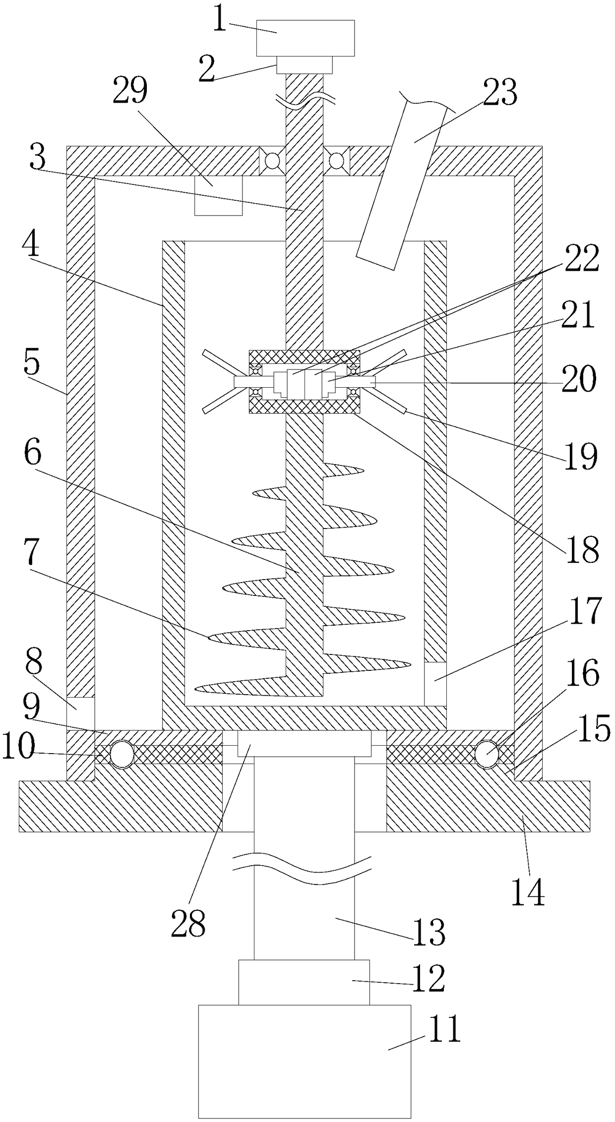
[0032] The purpose of the present invention is to provide a centrifugal sludge dewatering device, including a housing 5, a base 14, a centrifugal cylinder 4, a stirring mechanism, an ultrasonic generator 29, a first drive motor 1 and a second drive motor 11;

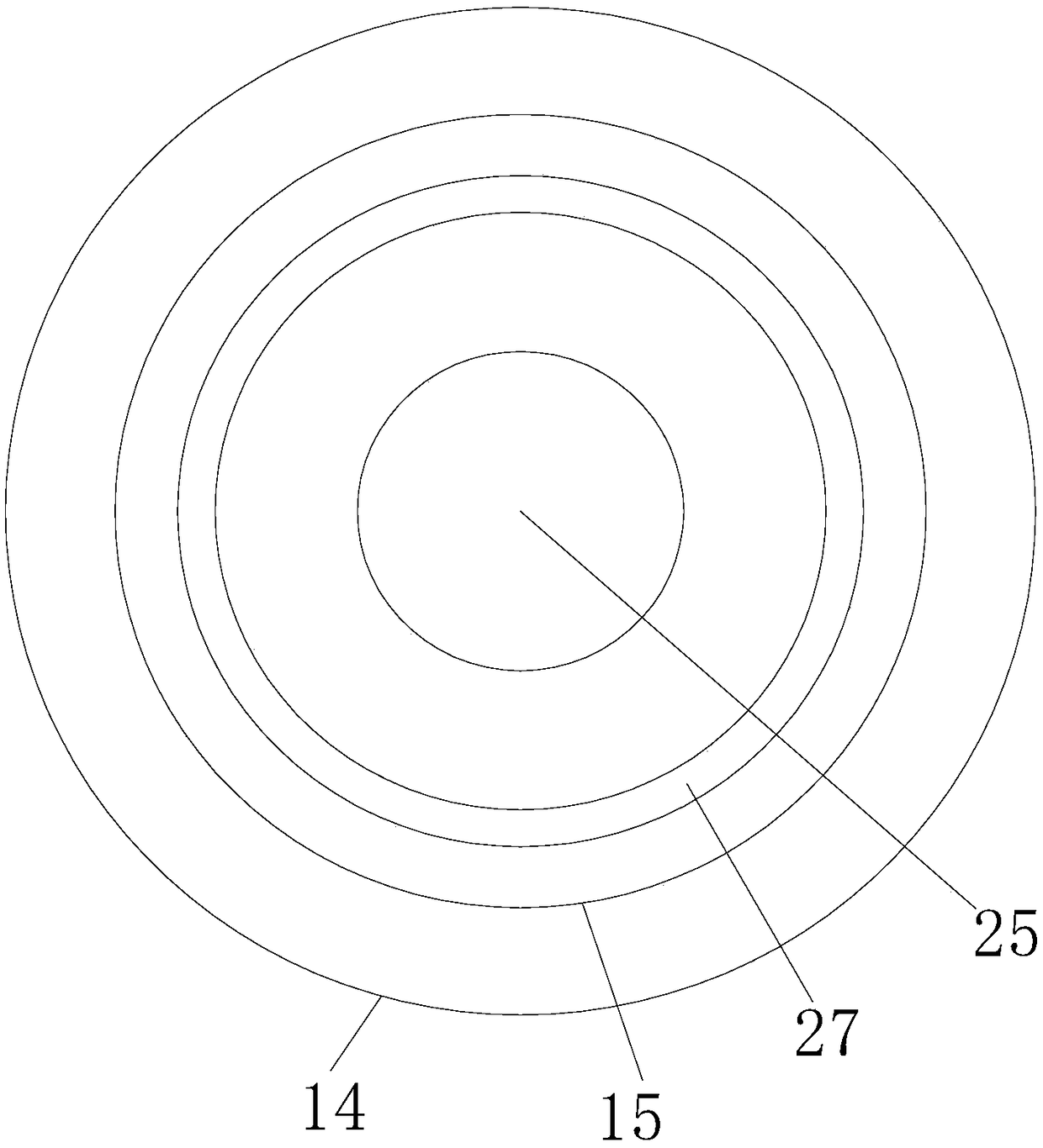
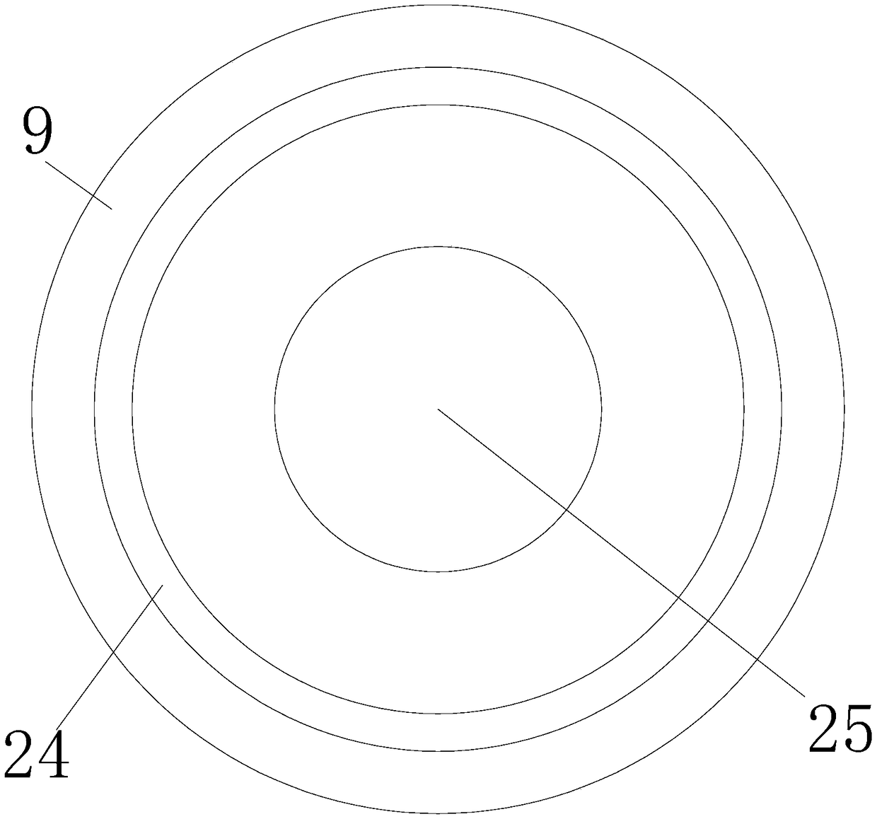
[0033] The shell 5 is a cylindrical structure and the shell 5 is turned upside down on the base 14 with the bottom facing upwards. The centrifugal cylinder 4 is coaxially arranged in the shell and the centrifugal cylinder 14 is fixedly arranged on the base 14 in a rotatable manner. , the second driving motor 11 drives the centrifugal cylinder 14 to rotate, the ultrasonic generator 29 is arranged on the inner side of the bottom of the casing 5 and the ultrasonic emission direction of the ultrasonic generator 29 is facing the mouth of the centrifugal cylinder 4;

[0034] The stirring mechan...


PUM


Abstract

The invention provides a centrifugal sludge dewatering device based on ultrasonic. The centrifugal sludge dewatering device comprises a shell, a base, a centrifugal cylinder, a stirring mechanism, anultrasonic generator, a first drive motor and a second drive motor, wherein the shell is of a cylindrical structure and the shell is buckled onto the base in an inverted manner that the bottom faces upwards; the centrifugal cylinder is coaxially arranged inside the shell and the centrifugal cylinder is rotatably fixedly arranged on the base; the second drive motor drives the centrifugal cylinder to rotate; the ultrasonic generator is arranged on the inner side of the bottom of the shell and the transmitting direction of the ultrasonic generator directly faces the cylinder opening of the centrifugal cylinder; and the stirring mechanism comprises an upper drive shaft, an installation box, two third drive motors, two transverse stirring shafts and a longitudinal stirring shaft. Sufficient dewatering can be carried out on sludge, a specified moisture content standard can be reached after sludge dewatering treatment, and further sterilization treatment is carried out by using ultrasonic inthe dewatering process, so that the device is beneficial to environmental protection.

Description

technical field [0001] The invention relates to sewage treatment equipment, in particular to an ultrasonic-based centrifugal sludge dewatering device. Background technique [0002] With the intensification of human production activities, a large amount of sewage will be produced in the production activities, and flocculation and sedimentation are required to form sludge in the process of sewage treatment. Since the sludge contains more than 95% of water, in order to protect the environment, it is necessary to Dehydration of sludge, the existing sludge dewatering equipment has the following defects: Existing sludge dewatering equipment in press dehydration, centrifugal dehydration and other methods, among them, although press dehydration can be more fully dehydrated, but the structure is complex, the equipment It is bulky and expensive to use, which is not conducive to miniaturized sludge treatment. Although the existing centrifugal dewatering is beneficial to miniaturized sl...

Claims


Application Information

Patent Timeline
Patent Type & Authority Applications(China)
IPC IPC(8): C02F11/12C02F11/00
CPCC02F11/004C02F11/127
Inventor 张沁王伟
Owner CHONGQING JIAOTONG UNIVERSITY
Learn More