Using method of horizontal type oil production and gas exhaust synchronous production device

A production device and horizontal technology, which is applied in the field of horizontal oil production and exhaust synchronous production devices, can solve problems such as power consumption, hidden dangers, and natural gas without hydrogen sulfide removal, and achieve the effect of avoiding the drop of dynamic liquid level.

Pending Publication Date: 2018-11-06
高新昀
View PDF7 Cites 3 Cited by
  • Summary
  • Abstract
  • Description
  • Claims
  • Application Information

AI Technical Summary

Problems solved by technology

But the problem is whether it only has the exhaust function, or it needs to shut down the well
However, the problem that it exists is that it only uses the power of the pumping unit to perform the exhaust function, and it cannot produce oil and exhaust at the same time.
This patent realizes the extraction of gas while producing oil, but its existing problems are: the air pump is installed vertically, which has certain safety hazards. In addi...

Method used


Image

  • Using method of horizontal type oil production and gas exhaust synchronous production device
  • Using method of horizontal type oil production and gas exhaust synchronous production device
  • Using method of horizontal type oil production and gas exhaust synchronous production device

Examples


Embodiment 1

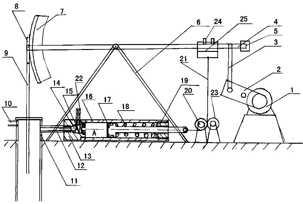
[0031] Embodiment 1, with reference to attached figure 1 , a kind of horizontal synchronous production device for oil extraction and exhaust mentioned in the present invention, its technical scheme is: comprise motor 1, power arm 2 of pumping unit, power connecting rod 3, beam 4, counterweight 5 of pumping unit, pumping unit Oil unit support 6, pumping unit donkey head 7, rope hanger 8, sealing polished rod 9, oil outlet 10, wellhead connecting nipple 11, motor 1 is connected to one end of power connecting rod 3 through the power arm 2 of the pumping unit, The other end of the power link 3 is connected to the rear side of the beam 4, and the other end of the beam 4 is connected to the donkey head 7 of the pumping unit. The middle part of the beam 4 is supported on the top of the support 6 of the pumping unit, and the end of the beam 4 is set There is a counterweight 5 of the pumping unit, and the donkey head 7 of the pumping unit is connected to the sealed polished rod 9 throu...

Embodiment 2

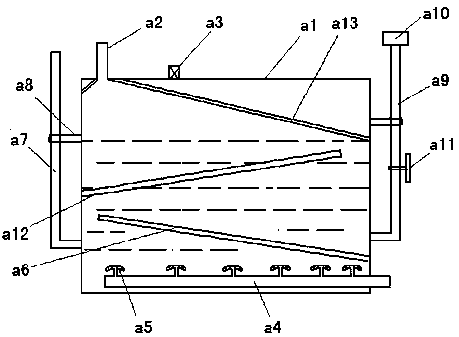
[0044] Embodiment 2, with reference to attached Figure 5 The difference between this embodiment and Embodiment 1 is that there are a plurality of ventilation pipes a14 distributed on the lower baffle plate a6 and the middle baffle plate a12, so that a small amount of gas enters the middle baffle plate a12 through the lower baffle plate a6 Below, also increases the gas and H 2 SO 3 The contact quantity of the solution; in addition, the distribution density of the umbrella-shaped spray heads a5 arranged on the air intake pipe a4 is also gradually reduced from right to left, that is, the spacing is getting larger and larger, so that the natural gas and sulfurous acid can be carried out better. In addition, in order to increase the number of air bubbles generated by the vent pipe, a stainless steel mesh can be placed on the top of the vent pipe, refer to the attached Figure 8 , increase the number of bubbles and increase the contact area with the liquid.

Embodiment 3

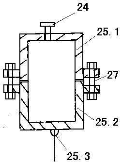
[0045] Embodiment 3, with reference to Figure 6 , the present invention differs from Embodiments 1 and 2 in that it does not need to be provided with a stay cord anti-off wheel 23, and the structure adopted is as follows: the stay cord can be directly connected to the counterweight 5 through the movable pulley 26, and there is no need to install a stay cord for positioning Block 25, the position that requires counterweight to install just meets the position requirement of stay rope at this moment; When the end of the beam of the oil machine goes down, the pull rope moves downward, and the return spring 18 is doing a return action. In this way, the pull rope on the side of the fixed pulley is recovered, and the torsion spring roller on the side of the auxiliary fixed pulley also drives the pull rope to recover , so that the pull rope does not fall off from the fixed pulley; when the beam goes up, one end of the pull rope pulls the suction piston to squeeze the return spring, a...


PUM


Abstract

The invention relates to a using method of a horizontal type oil production and gas exhaust synchronous production device. According to the technical scheme, an gas inlet pipe of a wellhead connectingshort section is connected to the horizontal type gas exhaust device, and a suction piston and a return spring are installed in an inner cavity of a horizontal type sealing cylinder liner; the outerend of the suction piston in the horizontal type sealing cylinder liner is connected to a draw cord position finding block by winding a fixed pulley through a draw cord, and the draw cord position finding block is installed at the rear end of a walking beam; the beam walking is driven by an electric motor to swing up and down, and the oil production is realized while gas exhausting. The using method of the horizontal type oil production and gas exhaust synchronous production device has the beneficial effects that the reciprocating motion of a walking beam type pumping unit is utilized to enable the horizontal type gas exhaust device to discharge natural gas in a casing in time, the weight principle of the walking beam type pumping unit and the conversion of potential energy and kinetic energy are utilized to enable a whole pumping system to be more energy-saving, and a horizontal type structure is more safe and reliable; and in addition, the discharge of the natural gas is realized synchronously, and the natural gas is subjected to preliminary removal of hydrogen sulfide to avoid the occurrence of a poisoning safety accident on field staff.

Description

technical field [0001] The invention relates to an oil production casing gas processing device, in particular to a method for using a horizontal oil production exhaust gas synchronous production device. Background technique [0002] In oil extraction, there are a large number of high-permeability wells, because there is a large amount of natural gas associated in the formation, but it is not enough to form a natural gas development well. In this way, in the process of oil extraction, due to the existence of a large amount of gas, the gas pressure in the casing of the oil well will be caused. However, the dynamic liquid level of the oil well will drop due to the increase of gas pressure, which will lead to insufficient liquid supply of the oil well. Therefore, the well must be stopped at this time, and then a large amount of gas in the casing must be released. After the gas is released, the casing will The dynamic fluid level of the pump can be raised to the normal height, an...

Claims


Application Information

Patent Timeline
IPC IPC(8): E21B43/00E21B43/34
CPCE21B43/121E21B43/127E21B43/34
Inventor 高新昀姚振华高峰吴东明
Owner 高新昀
Why Eureka
Try Eureka