Dual-coil magneto-rheological valve with damping gap being automatically adjusted in liquid flow direction

A magneto-rheological valve, automatic adjustment technology, applied in the direction of fluid pressure actuation device, valve details, valve device, etc., can solve the problems of complex control system, large space occupation, poor controllability, etc., and achieve a large adjustable range, The effect of stable working performance and wide adjustment range of pressure drop

Pending Publication Date: 2018-11-06
EAST CHINA JIAOTONG UNIVERSITY
View PDF0 Cites 1 Cited by
  • Summary
  • Abstract
  • Description
  • Claims
  • Application Information

AI Technical Summary

Problems solved by technology

[0004] In engineering applications, it is often required that the magnetorheological fluid has different pressure drops when the flow direction is different. Usually, two methods are used to realize it: one is to use the controller to monitor the direction of the fluid flow. When the fluid flow is reversed, change the magnetorheological valve. The size

Method used


Image

  • Dual-coil magneto-rheological valve with damping gap being automatically adjusted in liquid flow direction
  • Dual-coil magneto-rheological valve with damping gap being automatically adjusted in liquid flow direction
  • Dual-coil magneto-rheological valve with damping gap being automatically adjusted in liquid flow direction

Examples


Embodiment Construction

[0021] Below in conjunction with accompanying drawing and embodiment the present invention will be further described:

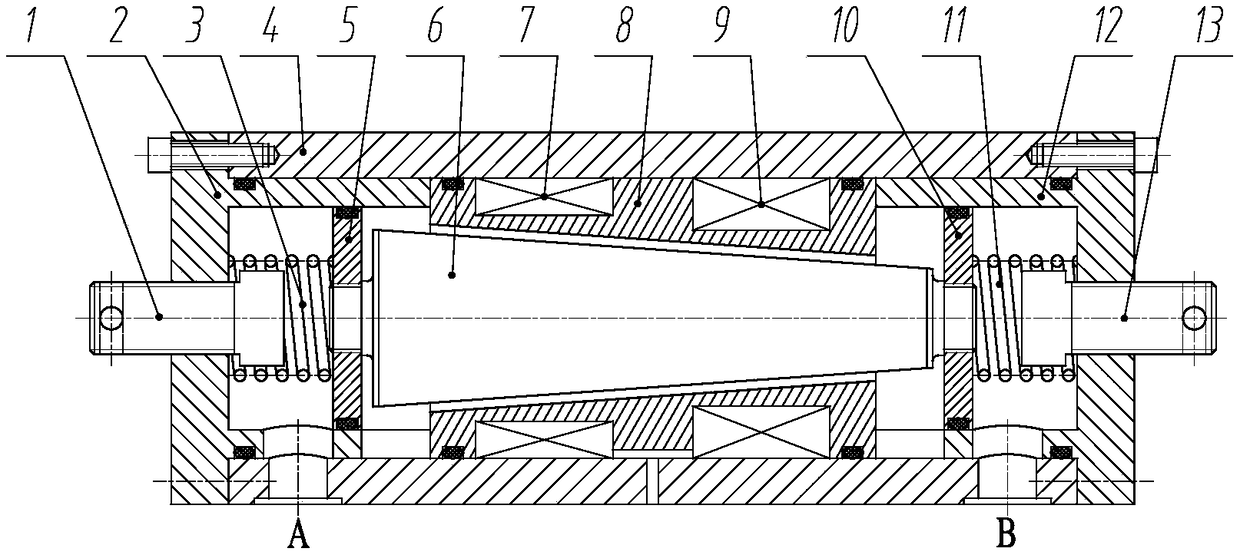
[0022] figure 1 Shown is the structure diagram of the present invention. Mainly include: left limit bolt 1, left end cover 2, left return spring 3, valve body 4, left spool piston 5, spool 6, left excitation coil 7, bobbin frame 8, right excitation coil 9, right spool Piston 10, right return spring 11, right end cover 12 and right limit bolt 13.

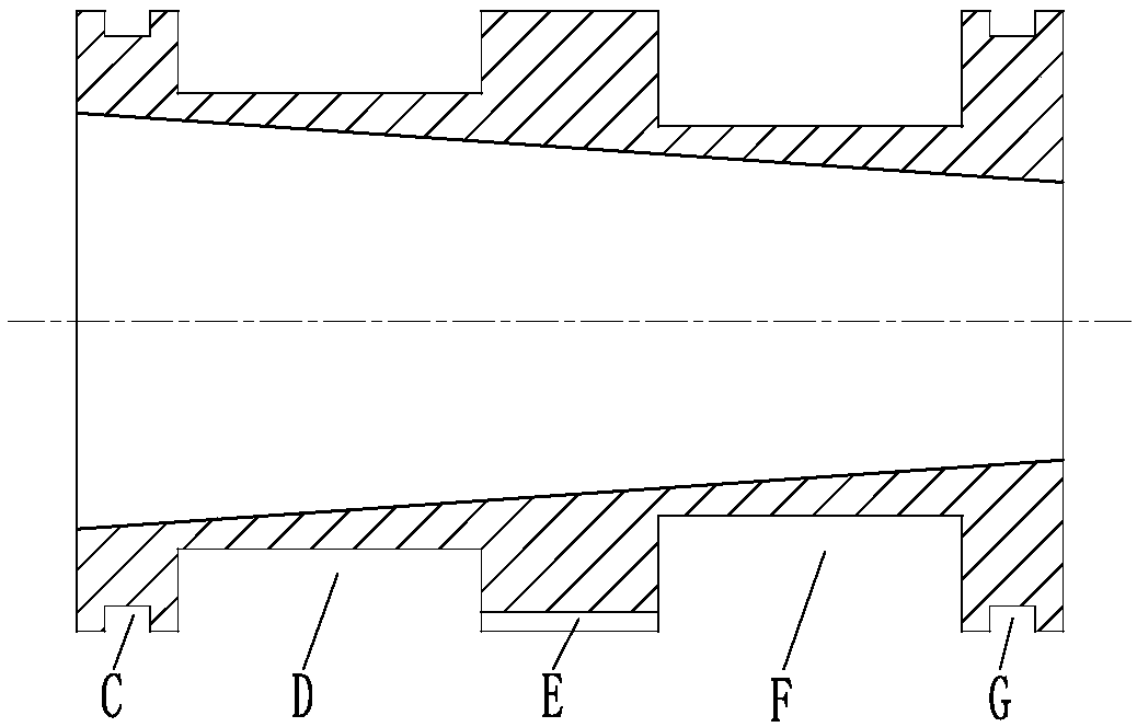
[0023] figure 2 Shown is the sectional view of the bobbin of the present invention. The winding frame 8 is processed with a sealing ring groove C, a sealing ring groove G, a lead wire groove E, a winding groove D and a winding groove F. The left excitation coil 7 is wound in the winding slot D of the bobbin 8 , the right exciting coil 9 is wound in the winding slot F of the bobbin 8 , and its lead wire is drawn from the valve body 4 through the lead slot E of the bobbin 8 . out of the lead hole.

[0024] im...


PUM


Abstract

The invention discloses a dual-coil magneto-rheological valve with damping gap being automatically adjusted in the liquid flow direction. The dual-coil magneto-rheological valve is mainly composed oflimiting bolts, end covers, reset springs, a valve body, a valve core, valve core pistons, field coils, a winding frame and the like. The gap between the winding frame and the valve body forms a conical liquid flow channel, and a plurality of sections of damping gaps are formed in the conical liquid flow channel under the action of electric currents in the field coils. Magneto-rheological liquid pushes the left valve core piston to drive the valve core to move rightwards when flowing from an A opening to a B opening, the damping gaps in the conical liquid flow channel are decreased, and the valve inlet-outlet pressure drop is increased; and the magneto-rheological liquid pushes the right valve core piston to drive the valve core to move leftwards when flowing from the B opening to the A opening, the damping gaps in the conical liquid flow channel are increased, and the valve inlet-outlet pressure drop is decreased. Under the condition that the magnitude of field currents is not changed, the dual-coil magneto-rheological valve can achieve the effect that the valve inlet-outlet pressure drop is automatically changed along with changing of the flowing direction of the magneto-rheological liquid, and the dual-coil magneto-rheological valve is especially suitable for a valve-controlled cylinder system requiring small circuit pressure.

Description

technical field [0001] The invention relates to a magneto-rheological valve, in particular to a double-coil magneto-rheological valve whose damping gap is automatically adjusted according to the direction of liquid flow. Background technique [0002] In the hydraulic control system, the hydraulic control valve is mainly used to control the pressure, flow and flow direction of the liquid flow in the hydraulic actuator, so as to control the start and stop of the hydraulic actuator, change the speed, direction, force and action sequence of the movement, etc. Meet the requirements of various hydraulic equipment for load conditions such as motion, speed, force and torque. Therefore, the performance of the hydraulic control valve directly affects the static characteristics, dynamic characteristics and working reliability of the hydraulic system, and is one of the core control units in the hydraulic control system. With the development of high technology, the engineering applicati...

Claims


Application Information

Patent Timeline
IPC IPC(8): F15B13/02F16K31/06
CPCF15B13/02F16K31/06Y02E10/20
Inventor 胡国良邓英俊喻理梵丁孺琦古成
Owner EAST CHINA JIAOTONG UNIVERSITY
Why Eureka
Try Eureka