Laser radar and laser radar control method

A laser radar and laser technology, applied in the detection field, can solve the problems of large receiving field of view, limited scanning range of a single galvanometer, and high requirements for the receiver

Pending Publication Date: 2018-11-06
SUTENG INNOVATION TECH CO LTD
View PDF5 Cites 17 Cited by
  • Summary
  • Abstract
  • Description
  • Claims
  • Application Information

AI Technical Summary

Problems solved by technology

Solid-state laser radar is a kind of laser radar. The existing solid-state laser radar mainly adopts the off-axis scheme, but the off-axis scheme also has relatively large defects, such as the receiving field of view is too large and the background noise is large, so the receiver's Higher requireme...

Method used


Image

  • Laser radar and laser radar control method
  • Laser radar and laser radar control method
  • Laser radar and laser radar control method

Examples


Embodiment Construction

[0051] The following embodiments of the present invention provide a laser radar and a laser radar control method, which can expand the scanning range of the laser radar and improve the resolution and accuracy of the laser radar.

[0052] The technical solutions in the embodiments of the present invention will be clearly and completely described below in conjunction with the accompanying drawings in the embodiments of the present invention. Obviously, the described embodiments are only some, not all, embodiments of the present invention. Based on the embodiments of the present invention, all other embodiments obtained by persons of ordinary skill in the art without creative efforts fall within the protection scope of the present invention.

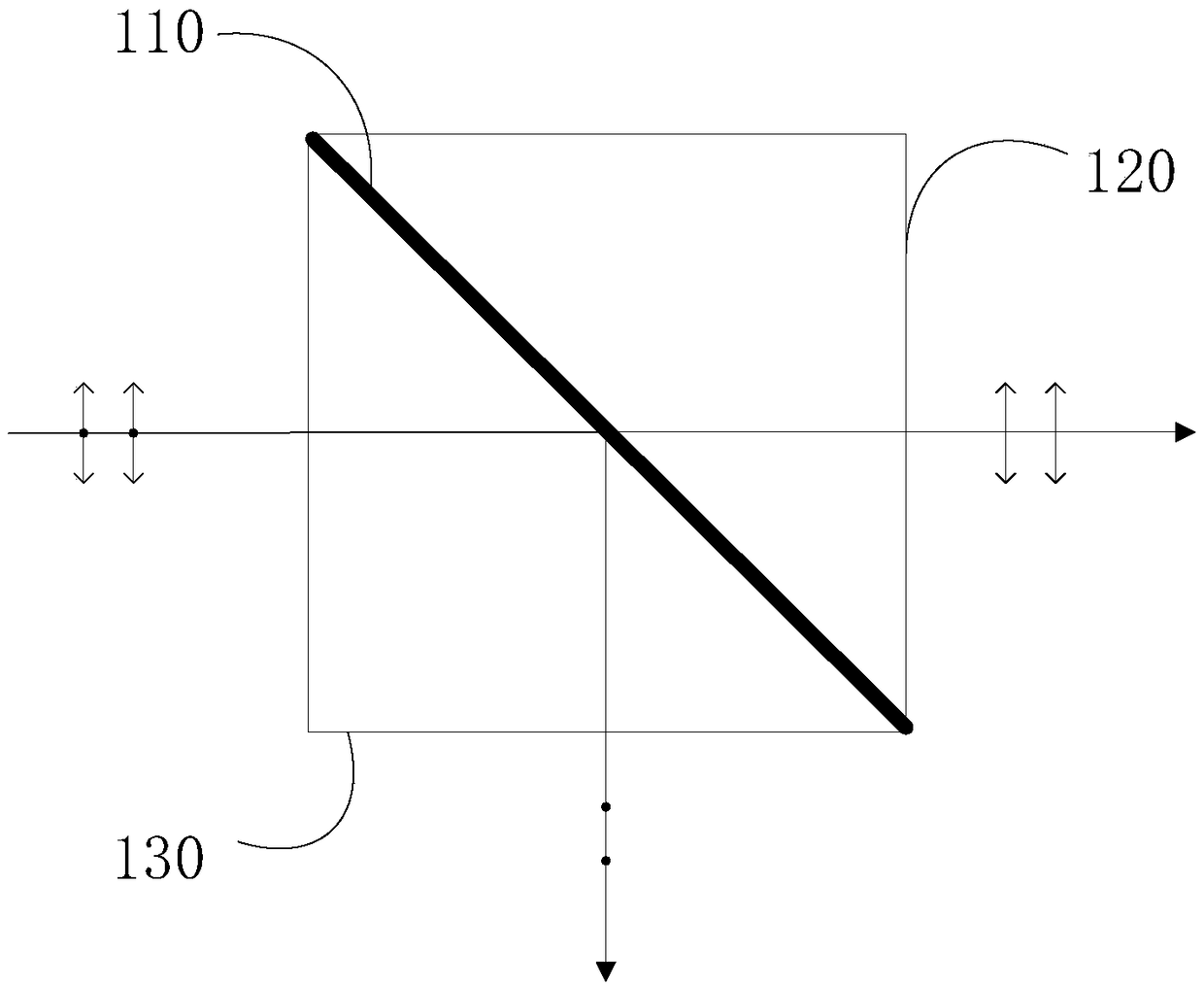
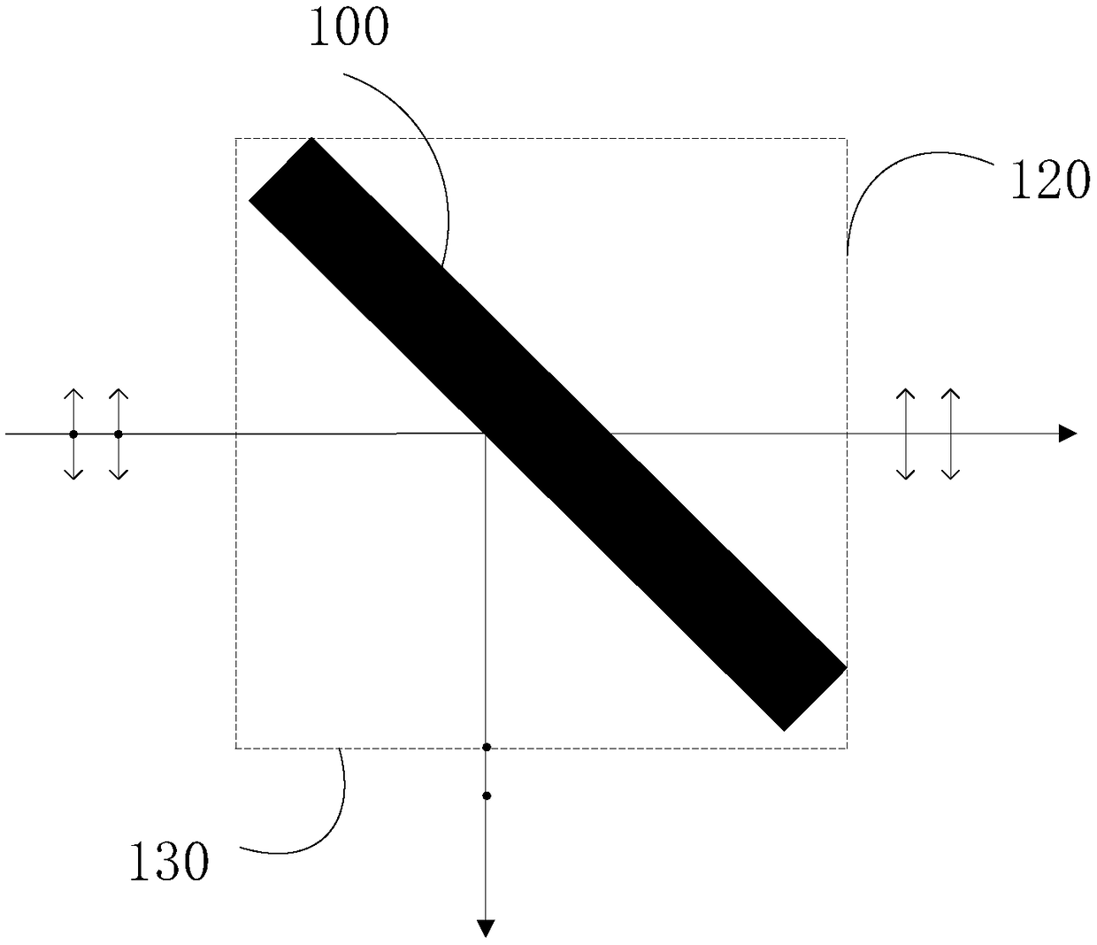
[0053] Before describing the lidar of the embodiment of the present invention in detail, the principle of the polarization splitting unit will be described first. The polarization beam-splitting unit includes a polarization beam-splitting p...


PUM


Abstract

The embodiment of the invention discloses a laser radar and a laser radar control method. The laser radar comprises two or more than two detection units, each detection unit comprises: one emitter configured to emit an emergent laser; one emitting terminal collimation unit configured to perform collimation of the emergent laser emitted by the emitter; one polarizing beam-splitting unit configuredto allow the emergent laser after collimation to enter from a first light port of the polarizing beam-splitting unit to allow the P polarized light in the emergent laser after collimation to be emergent from the emitting terminal collimation unit; a quarter-wave plate configured to allow the P polarized light emergent from the second light port of the emitting terminal collimation unit to become circular polarized light; and a galvanometric scanner configured to change the emergent direction of the circular polarized light to become the emergent laser. The laser radar and the laser radar control method can enhance the scanning range of the laser radar and improve the resolution and precision of the laser radar.

Description

technical field [0001] The invention relates to the detection field, in particular to a laser radar and a laser radar control method. Background technique [0002] Lidar is a radar system that emits laser beams to detect the position, speed and other characteristic quantities of the target. Its working principle is to first transmit the detection laser beam to the target, and then compare the received signal reflected from the target with the transmitted signal. After proper processing, the relevant information of the target can be obtained, such as target distance, azimuth, height, speed, attitude, and even shape and other parameters. [0003] Lidar usually includes a transmitter, an optical unit at the transmitting end, an optical unit at the receiving end, and a receiver. According to the relative position of the optical axis of the transmitting end and the receiving end, lidar can be divided into two types: off-axis and coaxial. Solid-state laser radar is a kind of las...

Claims


Application Information

Patent Timeline
IPC IPC(8): G01S7/481G01S17/02
CPCG01S7/4815G01S17/02
Inventor 邱纯鑫刘乐天
Owner SUTENG INNOVATION TECH CO LTD
Why Eureka
Try Eureka