
Curing thermal process spatial-temporal modeling method based on ISOMAP

A modeling method and curing heat technology, applied in design optimization/simulation, special data processing applications, instruments, etc., can solve the problems that model parameters cannot be obtained, accurate partial differential equation description of the curing process is difficult to obtain, and boundary conditions are complicated

Pending Publication Date: 2018-11-06
GUANGDONG UNIV OF TECH
View PDF1 Cites 6 Cited by
  • Summary
  • Abstract
  • Description
  • Claims
  • Application Information

AI Technical Summary

Problems solved by technology

Due to the very complex boundary conditions of the curing process and the influence of internal unknown disturbances, an accurate partial differential equation description of the curing process is difficult to obtain
The curing furnace belongs to the distributed parameter system (DPS). Although the partial differential equation structure of the curing furnace can be roughly obtained according to the law of heat transfer, there are still many model parameters that cannot be obtained.

Method used


Image

  • Curing thermal process spatial-temporal modeling method based on ISOMAP
  • Curing thermal process spatial-temporal modeling method based on ISOMAP
  • Curing thermal process spatial-temporal modeling method based on ISOMAP

Examples


Embodiment 1

[0054] The ISOMAP-based spatio-temporal modeling method of curing thermal process of the present embodiment:

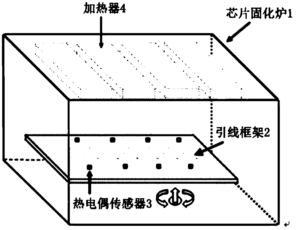
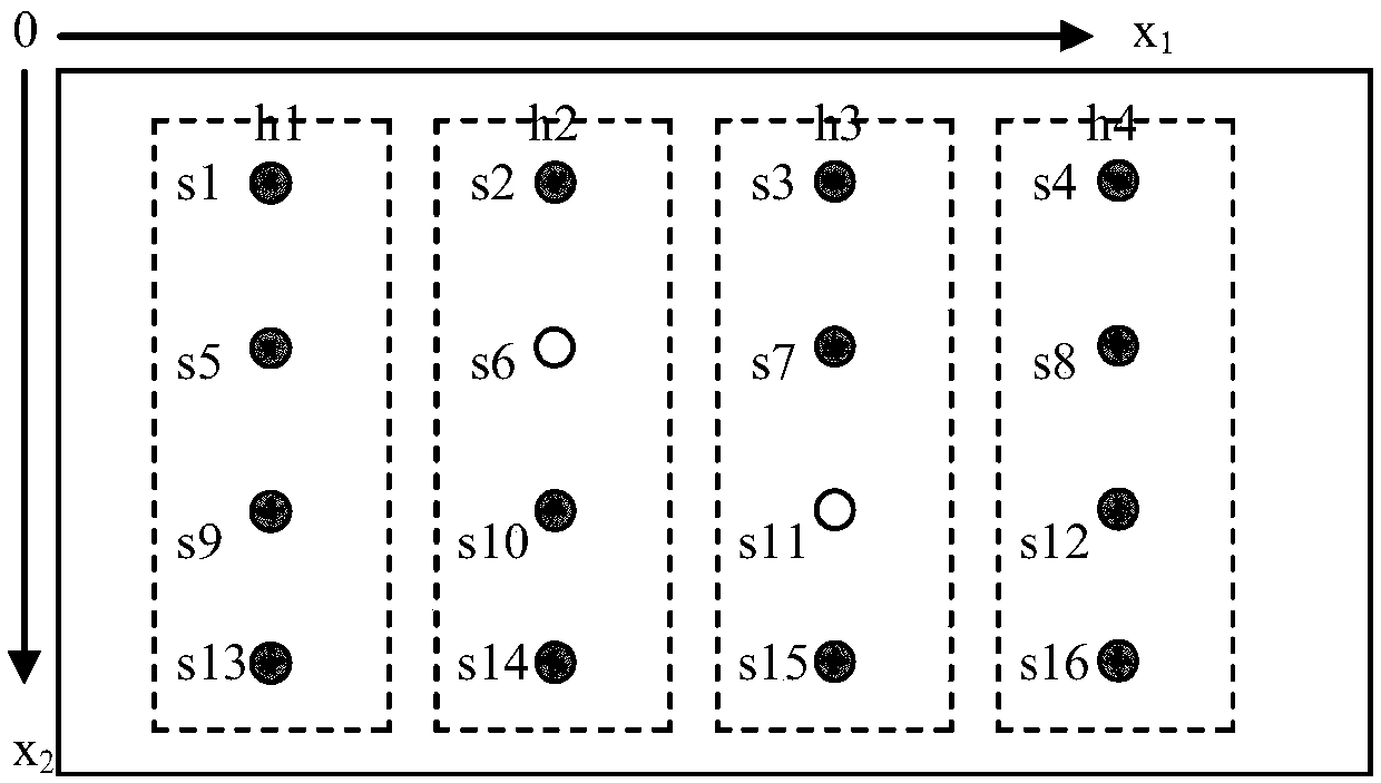
[0055] Step 1: Build a chip curing furnace temperature control platform, such as figure 1 , figure 2 As shown, a lead frame 2 is installed at the bottom of the furnace cavity of the chip curing furnace 1, and a plurality of thermocouple sensors 3 are evenly arranged on the upper surface of the lead frame 2, and the temperature data of all thermocouple sensors 3 are collected by the dSPACE real-time simulation platform, and the A plurality of heaters 4 are evenly arranged above the lead frame 2, and each heater 4 is provided with an input signal by a pulse width modulation signal and a power amplifier Make the chip curing furnace 1 perform curing work;

[0056] Step 2, the dSPACE real-time simulation platform counts the temperature data of all thermocouple sensors 3, and obtains the time-space data of the temperature distribution of the chip curing furnace 1 under ...

Embodiment 2

[0176] This example validates the proposed modeling method by conducting real-time experiments. First, build a chip curing furnace temperature control platform, such as figure 1 As shown, a lead frame 2 is installed at the bottom of the furnace chamber of the chip curing furnace 1, and 16 thermocouple sensors 3 of the same specification are evenly arranged on the upper surface of the lead frame 2. The detailed arrangement position of the thermocouple sensors 3 is as follows figure 2 shown. Four heaters 4 of the same specification are evenly arranged above the lead frame 2 , and the power of each heater 4 is 700w. The thermocouple sensors 3 are evenly arranged on the same horizontal plane 5 mm below the heater 4 . Each heater 4 is supplied with an input signal by a PWM signal and a power amplifier Make the chip curing furnace 1 perform curing work; the control input signal of the second heater h2 Such as Figure 5 shown. The temperature data of all thermocouple sensors ...


PUM


Abstract

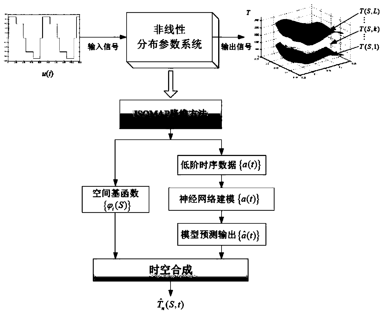
The invention discloses a curing thermal process spatial-temporal modeling method based on an ISOMAP. The method comprises the steps that first, a chip curing oven temperature control platform is setup; second, spatial-temporal data of temperature distribution changing over time of a chip curing oven in a curing working state is obtained; third, an ISOMAP algorithm is used to learn an orthogonalmapping function representing spatial nonlinear characteristics from the spatial-temporal data collected in the second step; and fourth, the ISOMAP algorithm is used to perform spatial-temporal variable separation on the high-dimensional spatial-temporal data through the orthogonal mapping function. By establishing a chip curing thermal process model, online temperature monitoring and online estimation of temperature distribution of the chip curing oven are realized, and modeling precision is high.

Description

technical field [0001] The invention relates to the field of curing thermal process modeling, in particular to an ISOMAP-based spatiotemporal modeling method for curing thermal process. Background technique [0002] In the chip packaging process, the curing process is one of the most important processes. The quality of chip curing directly affects the quality and service life of the final product. The equipment used in the curing process is the chip curing furnace. There is an arched heating module inside the curing furnace, and its function is to keep the temperature field in the furnace cavity consistent. There is a cooling device at the lower end of the furnace chamber, its function is to make the temperature in the furnace chamber form a temperature gradient in the up and down direction, which can meet the requirements of different temperatures required by the chip in different solidification stages. Due to the very complex boundary conditions of the curing process an...

Claims


Application Information

Patent Timeline
IPC IPC(8): G06F17/50
CPCG06F30/20
Inventor 杨海东徐康康
Owner GUANGDONG UNIV OF TECH
Learn More