Ultra-wideband common radiating aperture antenna unit

An aperture antenna and ultra-wideband technology, which is applied in the field of 18-40GHz ultra-wideband integrated radiation aperture antenna unit, can solve the problems of high profile, increased installation, commissioning, maintenance costs, and excessive distance.

Inactive Publication Date: 2018-11-06
10TH RES INST OF CETC
View PDF9 Cites 21 Cited by
  • Summary
  • Abstract
  • Description
  • Claims
  • Application Information

AI Technical Summary

Problems solved by technology

However, this antenna has several disadvantages: one is that it adopts a structure directly formed by metal, and the weight is relatively large; the other is that the distance between the feeder line and the support column is very small, which has a great influence on the impedance bandwidth, which will inevitably increase the installation and debugging. , maintenance cost; third, the distance between the two feeders of the antenna is too large, and the impedance consis

Method used


Image

  • Ultra-wideband common radiating aperture antenna unit
  • Ultra-wideband common radiating aperture antenna unit
  • Ultra-wideband common radiating aperture antenna unit

Examples


Embodiment Construction

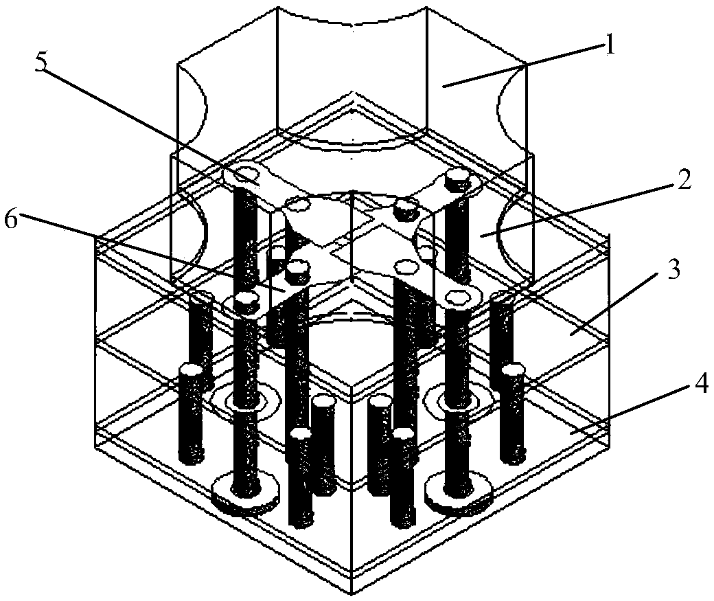
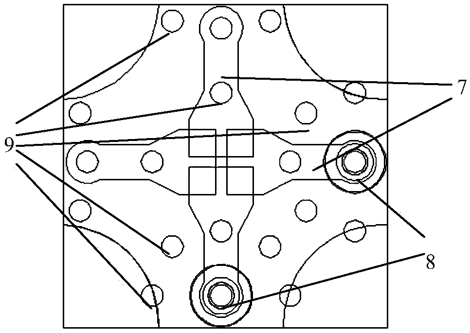
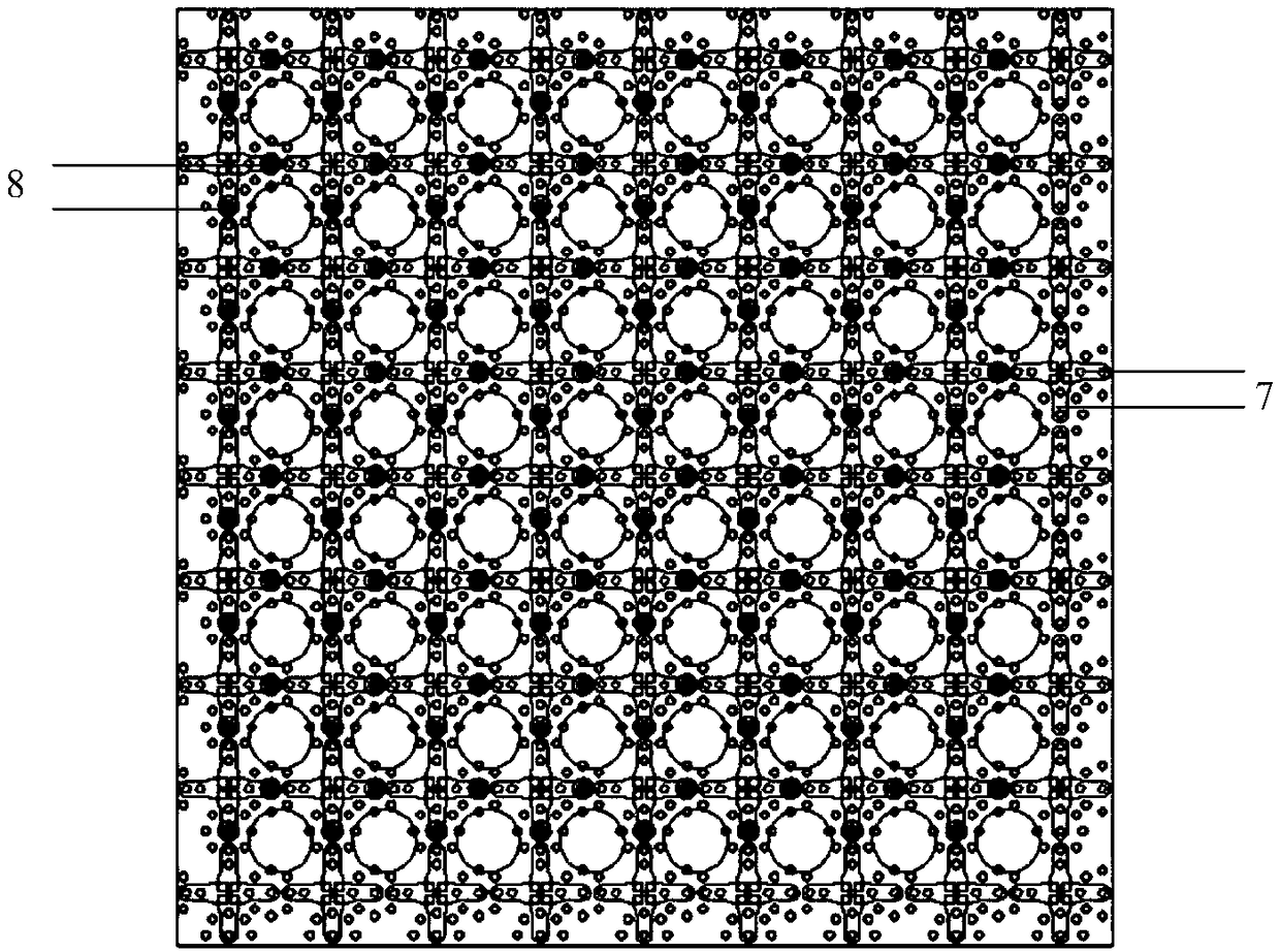
[0020] see Figure 1 to Figure 2 . In the embodiments described below, an ultra-wideband common aperture radiating antenna unit includes: at least three layers of rectangular dielectric plates supported and fixed by circumferential columns, and each layer of the dielectric plates is separated by an air layer with a thickness of at least 1 mm . In order to meet the requirements of actual use, the structure levels from top to bottom are impedance matching dielectric layer 1, strong coupling antenna dielectric layer 2, antenna dielectric layer 3, and impedance transformation dielectric layer in order from top to bottom, including a total of 4 layers. The antenna unit is a plane multi-layer microstrip form structure level with a size of 3.75mm×3.75mm×4mm. The impedance matching medium layer 1 is a wide-angle scanning aperture structure covering the radiation surface of the antenna, so as to realize impedance matching of the radiation aperture during wide-angle scanning. The str...


PUM


Abstract

An ultra-wideband common radiating aperture antenna unit disclosed by the invention aims to provide a broadband radiating aperture antenna unit with high polarization isolation, small insertion loss,capable of reducing antenna weight and reducing antenna loss. The invention is realized by the following technical solution, a strongly coupled antenna dielectric layer is embedded with cross-angulararc-coupled patches having adjacent cross-arcs in transition connection, the upper and lower surfaces are etched with cross-shaped microstrip dipole oscillator arm radiating patches, the microstrip dipole oscillator arm radiating patches are divided into symmetrical dipole pairs by four slotted lines, and the horizontal microstrip dipole pair and the vertical dipole pair are respectively located on upper and lower sides of the layer structure, so that the two dipole pairs are mostly used as the basic unit of the antenna, and in the space, represent in a structure of being separated by the cross partition, being correspondingly overlapped up and down, and being symmetrically coupled to the balanced feeding, thereby forming an ultra-wideband working antenna unit with high isolation, low cross polarization and strong coupling effect for generating mutual capacitive loading feed.

Description

technical field [0001] The invention relates to a broadband common aperture antenna widely used in the fields of aviation and aerospace, which can meet the requirements of ultra-wideband, multi-band, structural and functional platform integration of phased array antenna systems, especially 18-40GHz ultra-wideband integration requirements. Radiating Aperture Antenna Element. Background technique [0002] Microstrip antennas in the prior art have been paid attention to in many fields due to their small size, light weight, easy processing, etc., but microstrip antennas have low radiation gain. But in most applications, the form of antenna array is used. When the antenna elements form an antenna array, the structure and feeding method of the array elements have a great influence on the polarization characteristics and side lobes of the antenna array. When a dual-polarized microstrip antenna is used to form an antenna array element, on the one hand, the antenna is required to h...

Claims


Application Information

Patent Timeline
IPC IPC(8): H01Q1/38H01Q1/50H01Q9/04H01Q21/06
CPCH01Q1/38H01Q1/50H01Q9/045H01Q21/065
Inventor 王多何小峰任思张云何海丹
Owner 10TH RES INST OF CETC
Why Eureka
Try Eureka