Power transmission line travelling wave protection method considering travelling wave speed characteristic

A transmission line, traveling wave protection technology, applied in emergency protection circuit devices, electrical components, etc., can solve problems such as inability to meet the requirements of engineering promotion, changes in network topology, and difficulty in wave head identification, and achieve good use value and realization. Simple, low computational complexity

Active Publication Date: 2018-11-06
CHINA UNIV OF MINING & TECH
View PDF4 Cites 2 Cited by
  • Summary
  • Abstract
  • Description
  • Claims
  • Application Information

AI Technical Summary

Problems solved by technology

However, the above-mentioned traveling wave protection has problems such as difficulty in identifying subsequent wave heads and high risk of misoperation, and is easily affected by network topology changes and interference signals, which cannot meet the requirements of engineering promotion

Method used


Image

  • Power transmission line travelling wave protection method considering travelling wave speed characteristic
  • Power transmission line travelling wave protection method considering travelling wave speed characteristic
  • Power transmission line travelling wave protection method considering travelling wave speed characteristic

Examples


Embodiment Construction

[0026] The present invention will be further described below in conjunction with the accompanying drawings.

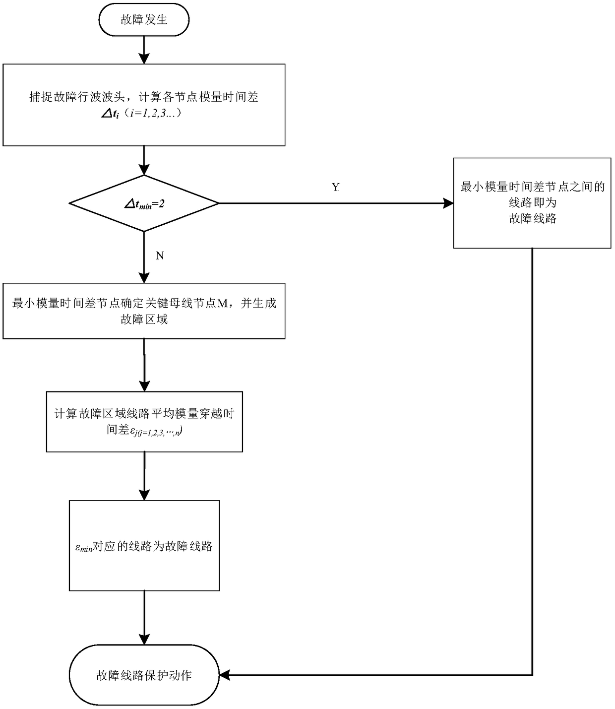
[0027] The transmission line traveling wave protection considering traveling wave velocity characteristics of the present invention, such as figure 1 As shown, the specific steps are as follows:

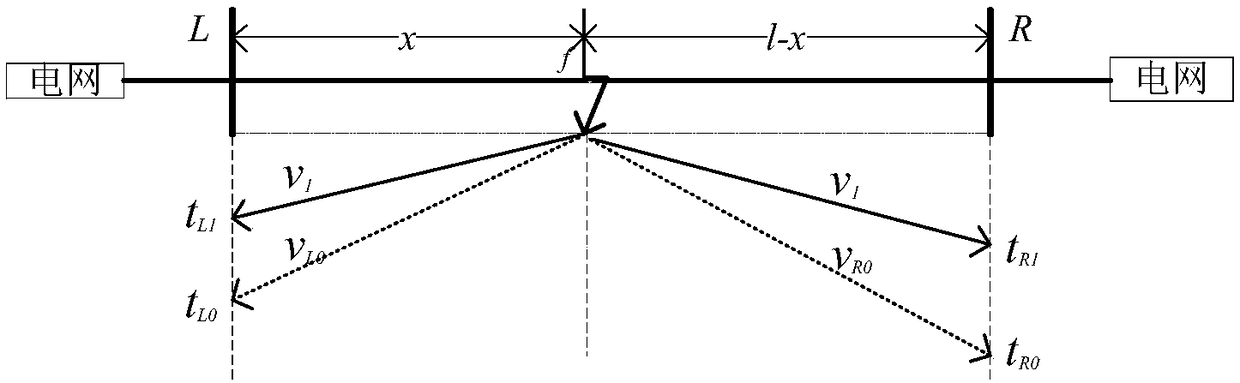
[0028] Step 1. When the line fails, the traveling wave detection device in each substation collects the transient current traveling wave signal at each bus node. The sampling rate of the traveling wave detection device is 1MHz, and the transient zero-mode signal is obtained by using the Clarke phase-mode transformation matrix and linear mode current; the discrete wavelet transform uses db6 wavelet, decomposes 4 layers, and takes the time corresponding to the modulus maximum value of the wavelet detail coefficient of layer d4 as the arrival time of the wave head. A space-time diagram with monitoring units at both ends of a line, such as figure 2 shown. Taking a line as an ...


PUM


Abstract

The invention discloses a power transmission line travelling wave protection method considering travelling wave speed characteristic. The method comprises the steps of acquiring a transient current travelling wave signal at each bus node in a power grid after a fault occurs in a line, and calculating to obtain modulus time difference between initial wavefront which are reached of a zero-mode travelling wave and a line-mode travelling wave of each bus node; taking the bus node with minimum modulus time difference as a key bus node; and determining a fault region according to the key bus node, calculating average modulus ride-through time difference of each circuit in the fault region, determining the circuit with minimum average modulus ride-through time difference as a fault circuit, and performing circuit protection action on the fault circuit. By the travelling wave protection method, two ends of the circuit do not need to be synchronous, the travelling wave protection method is freefrom influence of factors such as a system load, a fault initial phase angle and transition resistance, is high in reliability and accuracy and rapid in action speed and has relatively high economy and relatively high practical value.

Description

technical field [0001] The invention belongs to the field of transmission line protection, and in particular relates to a traveling wave protection method for transmission lines considering the characteristics of traveling wave velocity. Background technique [0002] Due to the unbalanced distribution of my country's main energy bases and power loads, the distance of power transmission is long and the span is long, and the terrain and environment passed by the transmission lines are varied, and they are easily affected by factors such as natural environment and external force damage, resulting in short circuits, Faults such as grounding. With the continuous expansion of the scale of the power system, the requirements for the safe and stable operation of the power grid continue to increase. The reliability of the transmission line plays a vital role in the economic life of a region. The safe operation of the power grid is of great significance. [0003] Compared with the tra...

Claims


Application Information

Patent Timeline
Patent Type & Authority Applications(China)
IPC IPC(8): H02H7/26
CPCH02H7/265
Inventor 梁睿王政刘成磊彭楠徐皓远孟祥震
Owner CHINA UNIV OF MINING & TECH
Why Eureka
Try Eureka