
A belt filter press used for printing and dyeing wastewater treatment

A belt-type filter press, printing and dyeing sewage technology, applied in the direction of adsorption water/sewage treatment, water/sewage multi-stage treatment, water/sludge/sewage treatment, etc., can solve the problem of reducing the speed of sludge conveyed by the filter belt and easy sedimentation For problems such as the bottom of the box and the mechanical loss of the body, it is convenient to filter and absorb again, improve the quality of cleaning, and increase the speed.

Inactive Publication Date: 2018-11-09
刘雪城
View PDF1 Cites 5 Cited by
  • Summary
  • Abstract
  • Description
  • Claims
  • Application Information

AI Technical Summary

Problems solved by technology

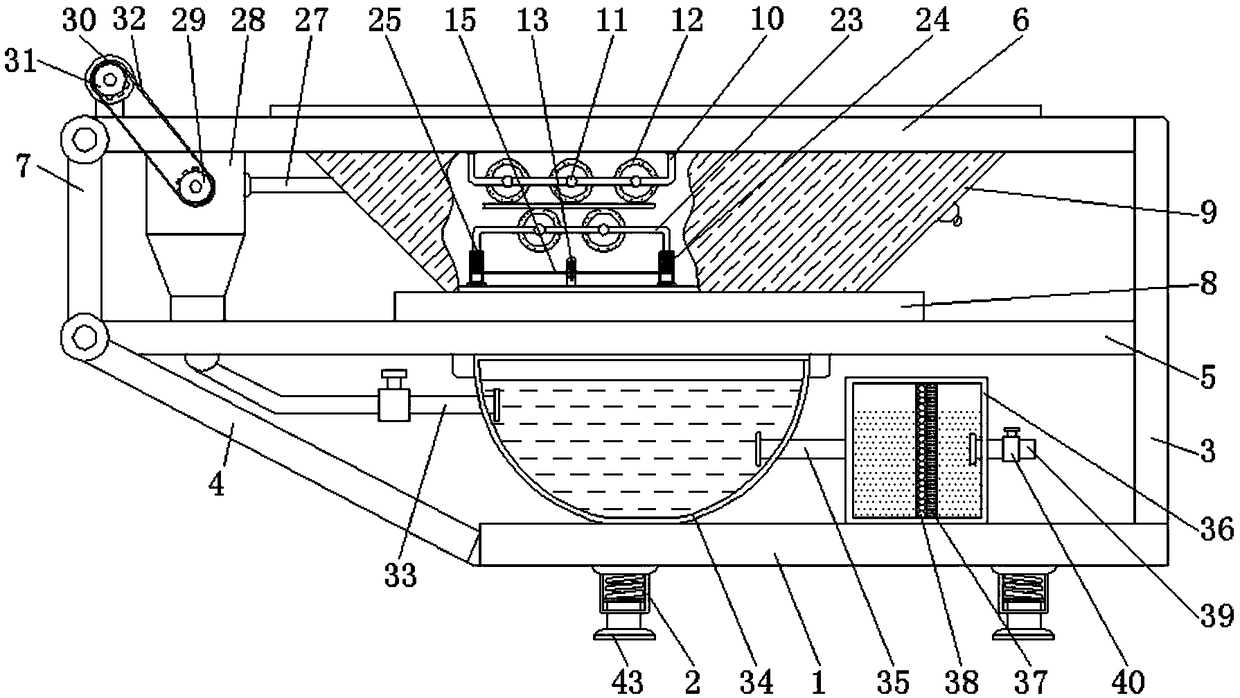
[0005] Aiming at the deficiencies of the comparative example, the present invention provides a belt filter press for printing and dyeing sewage treatment, which has the advantages of improving the speed of sludge transmission by the filter belt of the filter press, facilitating cleaning of the inside of the filter press and reducing the pressure of the filter press. The mechanical loss and other advantages solve the problem that the belt filter press does not clean the filter belt on the filter press, and then it is easy to reduce the speed of the sludge conveyed by the filter belt, and the sludge in the trapezoidal box of the belt filter press is easy to settle. The bottom of the box is not convenient for users to clean, and the belt filter press is not equipped with a shock absorber. When the machine is running, the friction between the bodies increases, which is easy to cause mechanical loss to the machine.

Method used


Image

  • A belt filter press used for printing and dyeing wastewater treatment
  • A belt filter press used for printing and dyeing wastewater treatment
  • A belt filter press used for printing and dyeing wastewater treatment

Examples


Embodiment Construction

[0027] The following will clearly and completely describe the technical solutions in the embodiments of the present invention with reference to the accompanying drawings in the embodiments of the present invention. Obviously, the described embodiments are only some, not all, embodiments of the present invention. Based on the embodiments of the present invention, all other embodiments obtained by persons of ordinary skill in the art without making creative efforts belong to the protection scope of the present invention.

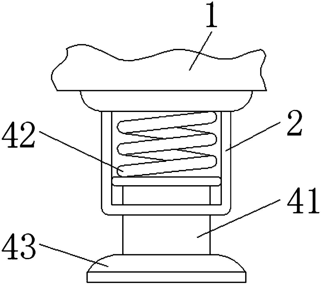
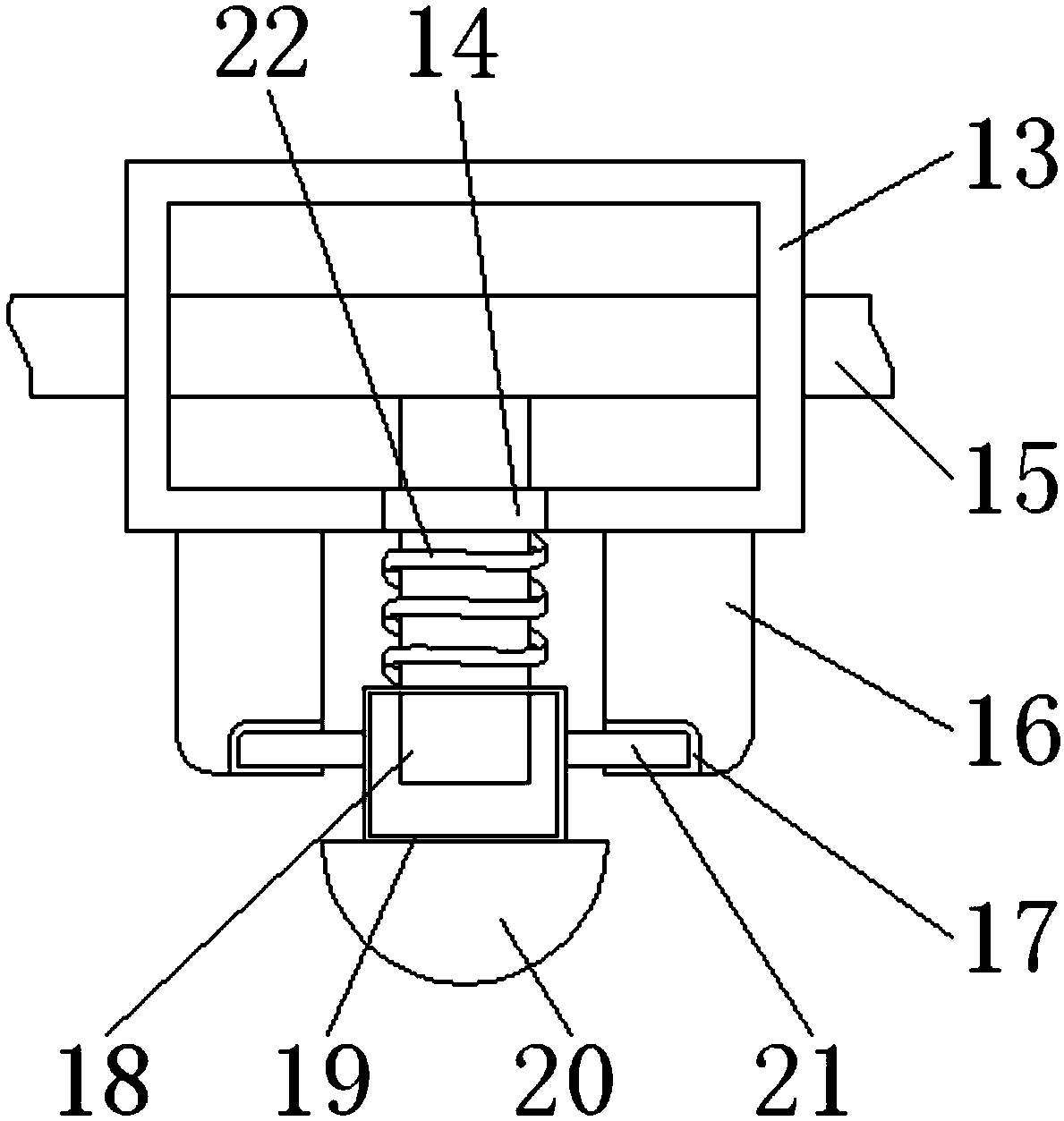
[0028] see Figure 1-5, a belt filter press for printing and dyeing sewage treatment, comprising a support plate 1, the left and right sides of the lower surface of the support plate 1 are fixedly installed with connecting pipes 2, and the interior of the connecting pipe 2 is movably sleeved with a fixed column 41, the fixed column The bottom end of the 41 penetrates the connecting pipe 2 and extends to the bottom of the connecting pipe 2. The bottom end of th...


PUM


Abstract

The invention relates to the technical field of printing and dyeing wastewater treatment related equipment, and discloses a belt filter press used for printing and dyeing wastewater treatment. The belt filter press includes a supporting plate. Connection pipes are fixedly mounted to left and right sides of the lower surface of the supporting plates. A vertical column is fixedly mounted on the right side of the upper surface of the supporting plate, and an inclined bar is fixedly connected to the left side of the supporting plate. The middle of the left side of the vertical column is fixedly connected to a connection plate. The left end of the connection plate is fixedly connected to the top end of the inclined bar. According to the belt filter press, through cooperation among a cross bar,limiting slots, a telescopic bar, a pull cap, a blocking bar and a shrinkable spring, a user can pull the pull cap to block the blocking bar in the limiting slots having different heights so that thedistance between upper and lower rotary rollers is changed indirectly, thus increasing pressure between the rotary cylinders and a filter belt, facilitating cleaning of impurities on the external surface of the filter belt by a user, and increasing the sludge conveying speed of the filter belt of the belt filter press.

Description

technical field [0001] The invention relates to the technical field of equipment related to printing and dyeing sewage treatment, in particular to a belt filter press for printing and dyeing sewage treatment. Background technique [0002] The dehydration process of the belt filter press can be divided into four important stages: pretreatment, gravity dehydration, wedge-shaped zone pre-press dehydration and press dehydration. The technology uses a new type of equipment filter program-controlled automatic box filter press, diaphragm filter press, deep sewage Mud dewatering filter press, integrated sewage sludge treatment equipment, online precision filtration system and other environmental protection filtration products with reasonable price and reliable performance. The mud cake in the common belt filter press will clump together during the reciprocating motion of the material sorting mechanism It becomes a large lump of mud. The mud sticks to the rake and cannot pass through...

Claims


Application Information

Patent Timeline
IPC IPC(8): B01D33/04B01D33/80F16F15/04C02F9/02
CPCB01D33/042B01D33/80C02F1/001C02F1/28
Inventor 刘雪城倪翔金见习
Owner 刘雪城
Learn More