
Gas expansion molding method

A molding method, gas expansion technology, applied in the field of gas expansion molding and composite material manufacturing, can solve the problems of unfavorable composite material manufacturing cost, application conditions of melting core mold and limited environment, etc., to shorten the molding cycle and shorten the manufacturing cost , The effect of shortening the process flow

Active Publication Date: 2018-11-09
AEROSPACE INST OF ADVANCED MATERIALS & PROCESSING TECH
View PDF3 Cites 0 Cited by
  • Summary
  • Abstract
  • Description
  • Claims
  • Application Information

AI Technical Summary

Problems solved by technology

[0006] The invention provides a gas expansion molding method, which can solve the technical problems in the prior art that the use of rubber molds to prepare products is not conducive to reducing the manufacturing cost of composite materials, and the application conditions and environment are limited when using molten core molds.

Method used


Image

  • Gas expansion molding method
  • Gas expansion molding method
  • Gas expansion molding method

Examples


Embodiment 1

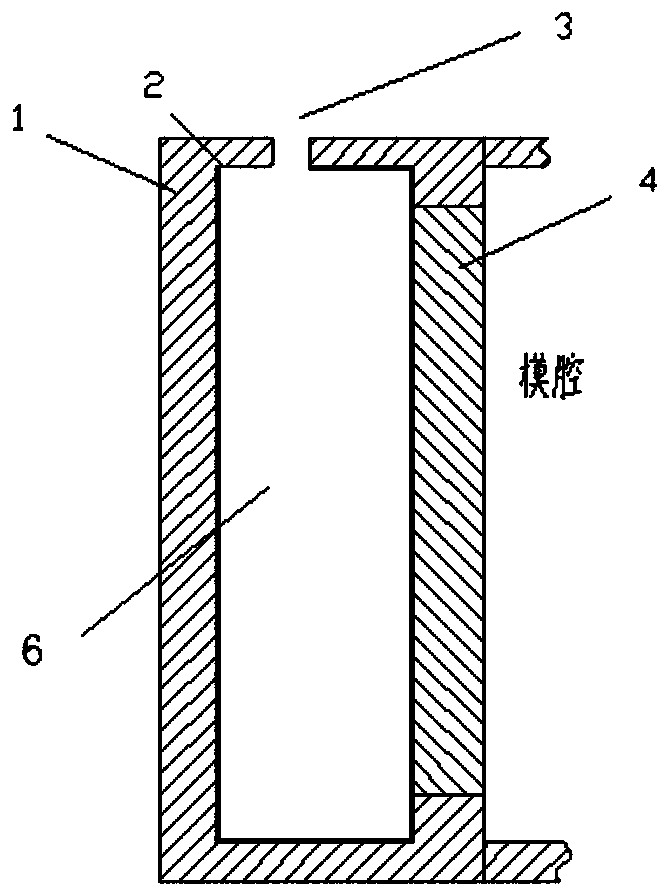
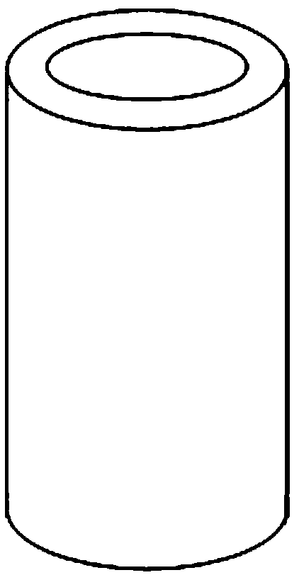
[0071] Such as Figure 2-3 As shown, the barrel-shaped composite shell was prepared using the hand lay-up process + pressurized form.

[0072] 1) Preparation of raw material preforms, use glass fiber and room temperature epoxy resin to paste product preforms according to the number of layers and structural requirements required by the design;

[0073] 2) Preparation of expansion material fluid, mixing aluminum, hydrochloric acid solution with a mass fraction of 10%, water, and gypsum according to a certain ratio and process requirements, and the mixing time is about 5 minutes;

[0074] 3) The pouring of the material will be as figure 2 The ready-to-use mold shown is cleaned and assembled, with inflatable material poured through the openings, assisted by mechanical vibration;

[0075] 4) Pressurize the core mold and solidify the resin. After the preform is prepared, the mold is closed, and it is controlled to start curing 30 minutes after the expansion material fluid is mixe...

Embodiment 2

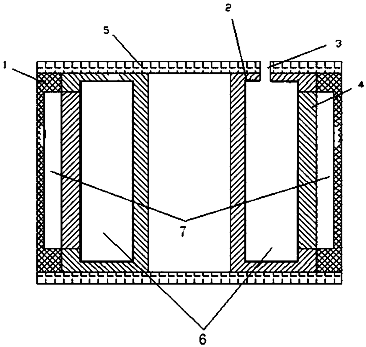
[0079] Such as Figure 4-5 As shown, a composite box-shaped part is prepared using a prepreg lay-up + molding format.

[0080] 1) Preparation of raw material prefabricated parts, using carbon fiber prepreg to lay out product preformed parts according to the number of layers and structural requirements required by the design;

[0081] 2) Preparation of expansive material fluid, mixing aluminum, 40% sulfuric acid solution by mass fraction, gypsum, water, water reducer, retarder, and cement according to a certain ratio and process requirements, and the mixing time is about 5 minutes;

[0082] 3) The pouring of the material will be as Figure 4-5 The ready-to-use mold shown is cleaned and assembled, with expansion material fluid poured through the openings, assisted by mechanical vibrations;

[0083] 4) Forming pressurization and resin curing of the mandrel. After the preformed part is prepared, the mold is closed, placed on the press, and the temperature starts to rise. The tem...


PUM


Abstract

The invention provides a gas expansion molding method, which comprises the following steps: a push plate is arranged in a mold cavity of a mold according to the shape of a product, the push plate divides the mold cavity into a first cavity and a second cavity, and the first cavity is provided with an opening; a raw material is disposed in the mold; preparing a fluid of an expanding material by mixing raw materials including reactants, a hardening component and water; rapidly pouring the fluid of the expanding material into the first cavity for filling, sealing the opening of the first cavity to form a closed first cavity, expanding a matrix generated by a reaction between the hardening component and water through gas generated by a chemical reaction of the reactants in the fluid of the expanding material so as to push the push plate for pressurizing the raw material for moulding, and letting the fluid of the expanding material form a destructible core mold after the moulding; and opening the first cavity, damaging the core mold and demoulding. The problem in the prior art that the use of a rubber mold for the preparation of a product is not beneficial to reduce the manufacture costof the composite material and the application conditions and environments are limited when a molten core mold is used is solved.

Description

technical field [0001] The invention relates to the technical field of composite material manufacture, in particular to a gas expansion molding method used for the manufacture of composite materials. Background technique [0002] Fiber-reinforced thermosetting composite material is a commonly used material in the aerospace field. The amount used has become a standard to measure whether the design and manufacture are advanced, whether it has high technology content, and whether the whole system has advantages. It has become an advanced material that designers are vying to adopt. one. However, with the process of lightening the structure and reducing the cost, designers are required to integrate or form the whole parts at one time, so as to reduce the amount of fasteners and adhesive joints and shorten the subsequent processing and assembly processes, which leads to composite The structure of material components is more complex, the technical requirements are higher, and the ...

Claims


Application Information

Patent Timeline
Patent Type & Authority Applications(China)
IPC IPC(8): B29C70/44
CPCB29C70/446
Inventor 毕向军许亚洪
Owner AEROSPACE INST OF ADVANCED MATERIALS & PROCESSING TECH
Learn More