Thermal management system of new energy vehicle
A thermal management system and new energy vehicle technology, applied in electric vehicles, vehicle components, air handling equipment, etc., can solve problems such as increased cost, low energy efficiency ratio, poor heat exchange effect, etc., and achieve a reasonable effect of heat energy utilization
- Summary
- Abstract
- Description
- Claims
- Application Information
AI Technical Summary
Problems solved by technology
Method used
Image
Examples
Embodiment 1
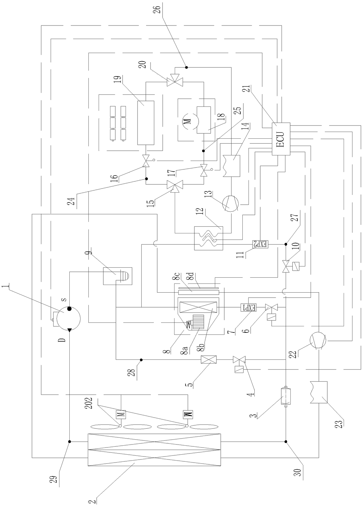
[0051] like figure 1 As shown, a thermal management system of a new energy vehicle includes a compressor 1, a condenser, a first expansion valve 7, and an HVAC 8, and the air outlet of the compressor 1 communicates with the inlet of the condenser through a first pipe 29 , the outlet of the condenser communicates with the inlet of the first expansion valve 7 through the second pipe 30, the outlet of the first expansion valve 7 communicates with the inlet of the evaporator 8b of HVAC8, and HVAC8 is for Heating Ventilation and Air Conditioning The English abbreviation is the heating ventilation and air conditioning system, which is the existing structure in the current air conditioning system, which includes a blower 8a, an evaporator 8b and a warm air core 8c, wherein the blower 8a is used to provide flowing wind to blow the air When entering the car, the evaporator 8b is used to exchange heat between the flowing air and the refrigerant, while the warm air core 8c is used to gen...
Embodiment 2
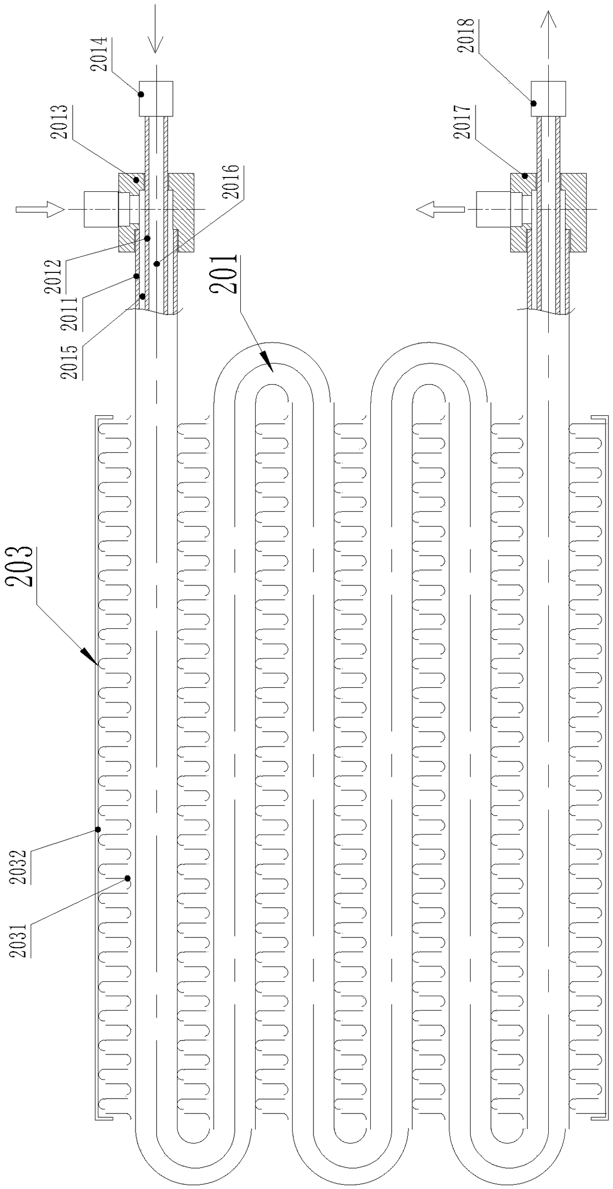
[0069] The structure of this embodiment is similar to that of Embodiment 1, except that the structure of the condenser body 201 and the module body 1202 is different from that of Embodiment 1. The structure of Embodiment 1 uses a coil structure to extend the refrigerant and water The heat exchange time is long, but in this embodiment, straight pipes are used to increase the heat exchange efficiency by increasing the flow of refrigerant and water.
[0070] like Figure 10 and Figure 13As shown, the number of the high-temperature refrigerant flow pipes 2012 and the first water flow pipes 2011 are multiple and all are straight pipes, the heat conduction fins 203 are arranged between adjacent straight pipes, and the first water inlet The joint 2013, the first water outlet joint 2017, the first refrigerant inlet joint 2014 and the first refrigerant outlet joint 2018 are all tubular structures and respectively provided with a first water inflow main channel, a first water outflow ...
PUM
 Abstract
Description
Claims
Application Information
 - R&D
- Intellectual Property
- Life Sciences
- Materials
- Tech Scout
- Unparalleled Data Quality
- Higher Quality Content
- 60% Fewer Hallucinations
Browse by: Latest US Patents, China's latest patents, Technical Efficacy Thesaurus, Application Domain, Technology Topic, Popular Technical Reports.
© 2025 PatSnap. All rights reserved.Legal|Privacy policy|Modern Slavery Act Transparency Statement|Sitemap|About US| Contact US: help@patsnap.com


