
Microwave broadband instant frequency measurement receiving system

An instantaneous frequency measurement and receiving system technology, applied in the field of frequency measurement, can solve the problems of affecting the performance of frequency measurement reception, long passing time, large volume, etc.

Pending Publication Date: 2018-11-09
上海频语电子技术有限公司
View PDF0 Cites 0 Cited by
  • Summary
  • Abstract
  • Description
  • Claims
  • Application Information

AI Technical Summary

Problems solved by technology

[0003] With the development of digital technology and the improvement of the operating frequency of electronic components, various new instantaneous frequency measurement technologies continue to emerge, but the existing frequency measurement receiving system has low frequency measurement accuracy, large volume, high power consumption and long transit time. , which seriously affects the performance of the frequency measurement receiver

Method used


Image

  • Microwave broadband instant frequency measurement receiving system
  • Microwave broadband instant frequency measurement receiving system
  • Microwave broadband instant frequency measurement receiving system

Examples


Embodiment Construction

[0027] In order to make the purpose, technical solution and advantages of the present application clearer, the present application will be further described in detail below in conjunction with the accompanying drawings and embodiments. It should be understood that the specific embodiments described here are only used to explain the present application, and are not intended to limit the present application.

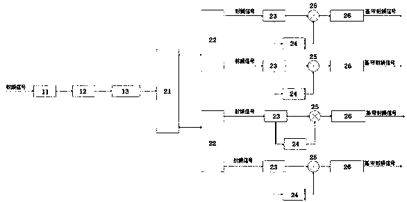
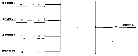
[0028] Please refer to Figure 1-Figure 4 , figure 1 A structural block diagram of a specific embodiment of the microwave broadband instantaneous frequency measurement receiving system provided by the present invention; figure 2 for figure 1 The partial structural block diagram of the signal conversion unit and the programmable gate array unit in the microwave broadband instantaneous frequency measurement receiving system shown; image 3 with Figure 4 for figure 1 The block diagram of the partial structure of the power distribution unit in the microwave broadband in...


PUM


Abstract

The invention relates to a microwave broadband instant frequency measurement receiving system, which comprises a radio frequency processing unit, a power distribution unit, a signal conversion unit and a programmable gate []array unit, wherein the ratio frequency processing unit is used for receiving radio frequency signals; the radiation frequency processing unit converts the input radio frequency signals into first baseband signals to be output; the power distribution unit is used for receiving the first baseband signals and allocates the signals to form at least two paths of second basebandsignals to be output; the signal conversion unit is used for receiving each path of second baseband signals in a one-to-one corresponding way; each second base band signal is converted to the presetfrequency and is then output; the programmable gate array unit is used for receiving each second baseband signal, and after []looking-up table operation, the programmable gate array unit outputs multipath parallel frequency state code or high-speed optical signals through a driver. The frequency measurement precision of the equipment is high; the EMS being smaller than 3 MHz can be reached; the size is small; the weight is light; the power consumption is low; the passing time is short; the operation is convenient.

Description

technical field [0001] The present application relates to the technical field of frequency measurement, in particular to a microwave broadband instantaneous frequency measurement receiving system. Background technique [0002] Instantaneous frequency measurement technology was first developed by MULLARD laboratory in the 1950s. Subsequently, the SYVACUSE University Research Center and STANFORD Research Institute in the United States also began to study. The early analog IFM is usually realized by using waveguide microwave components, traveling wave tubes and cathode ray displays. The system is large in size and complex in structure, and is generally only used on ground equipment and larger platforms. The emergence of broadband stripline couplers and solid-state gallium arsenide amplifiers has significantly reduced the size of microwave components. In the 1970s and 1980s, IFMs using such improved components and digital processing began to appear. [0003] With the developme...

Claims


Application Information

Patent Timeline
IPC IPC(8): H04B17/20
CPCH04B17/20
Inventor 王晓平毛智德刘昆宋波
Owner 上海频语电子技术有限公司
Learn More