Synchronous servo electric spindle of precision numerical control machine tool

A precision numerical control and servo electric technology, applied in the direction of electromechanical devices, control mechanical energy, electrical components, etc., can solve the problems of large rotor power consumption, heat generation, loss of rotation, and large vibration, so as to facilitate turning processing, reduce thermal errors, and work. The effect of low heat consumption

Pending Publication Date: 2018-11-13
广东中聪智能装备有限公司
View PDF13 Cites 0 Cited by
  • Summary
  • Abstract
  • Description
  • Claims
  • Application Information

AI Technical Summary

Problems solved by technology

[0004] At present, the asynchronous motorized spindle is commonly used. Although this type of motorized spindle overcomes the shortcomings of low speed, large vibration and high noise, it uses an asynchronous motor with a large volume, and the power consumption of the stator and rotor of the motor is large. , the efficiency is low, and in the case of the same power level, the loss of rotation is serious under the impact load, or even stalled, resulting in the inability to exert the performance of the machine tool. However, the existing electric spindle is through the sleeve casting outside the electric spindle Set up a cooling water column, and pass coolant into the cooling water column to realize the cooling of the electric spindle; since the cooling water column can only be set on both sides of the electric spindle, and cannot fully contact with the surrounding of the spindle, the problem is that the cooling is uneven and incomplete , and then the processing accuracy cannot be guaranteed, and the service life is short

Method used


Image

  • Synchronous servo electric spindle of precision numerical control machine tool
  • Synchronous servo electric spindle of precision numerical control machine tool
  • Synchronous servo electric spindle of precision numerical control machine tool

Examples


Embodiment Construction

[0019] The following are only preferred embodiments of the present invention, and therefore do not limit the protection scope of the present invention.

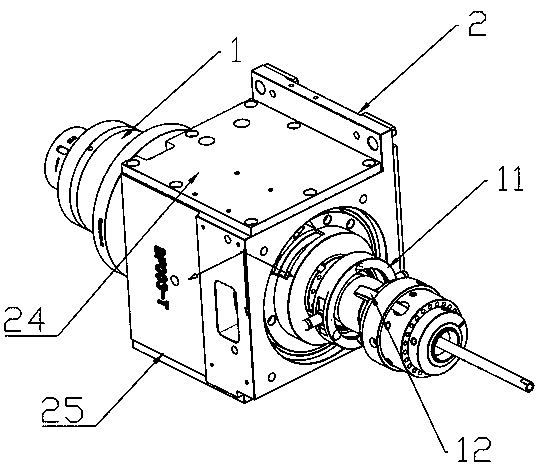
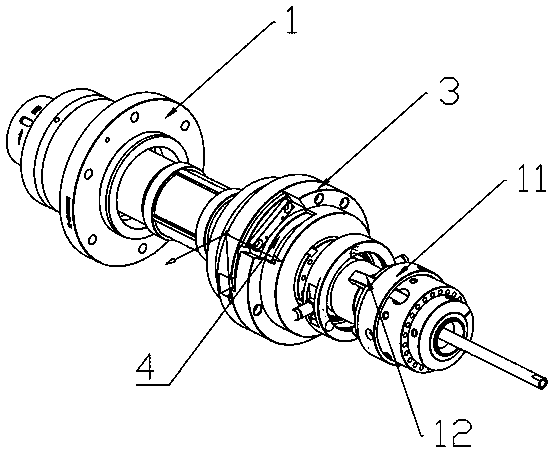
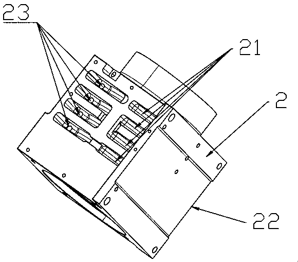
[0020] Such as Figure 1 to Figure 4 The synchronous servo electric spindle 1 of a precision numerical control machine tool shown includes a spindle 1, a sleeve casting 2, a stator 3 and a permanent magnet rare-earth rotor 4. There is an installation chamber inside the sleeve casting 2, and the stator 3 is installed on The installation chamber, the main shaft 1 is set in the stator 3, and the permanent magnet rare earth rotor 4 is fixedly arranged on the shaft body of the main shaft 1, and drives the main shaft 1 to rotate under the action of magnetic force; the stator and the rotor of the present invention are made of permanent magnetic rare earth materials , and the use of the output mode of the synchronous motor makes the overall volume of the synchronous servo electric spindle 1 small, the stator and rotor of the motor ge...


PUM


Abstract

The invention discloses a synchronous servo electric spindle of a precision numerical control machine tool. The synchronous servo electric spindle comprises a spindle, a sleeve casting, a stator and apermanent magnet rare-earth rotor, wherein a mounting chamber is arranged in the sleeve casting; the stator is mounted in the mounting chamber; the spindle is mounted in the stator in a sleeved manner; the permanent magnet rare-earth rotor is fixedly arranged at the spindle body of the spindle, and drives the spindle to rotate under magnetic force; a plurality of first cooling grooves are formedin the upper surface of the sleeve casting in the arrangement direction of the spindle; a plurality of second cooling grooves are formed in the lower surface of the sleeve casting in the arrangement direction of the spindle; and side cooling grooves used for communicating the first cooling grooves and the second cooling grooves are formed in the left side surface and the right side surface of thesleeve casting. The synchronous servo electric spindle disclosed by the invention has the advantages of being even in temperature drop, high in processing precision, long in service life, small in size, practical, low in speed, large in torque, and labor-saving in clamping.

Description

technical field [0001] The invention relates to the technical field of numerical control machine tools, in particular to a synchronous servo electric spindle of a precision numerical control machine tool. Background technique [0002] At present, in the machinery industry, in order to meet people's continuous improvement in the performance of mechanical products, the processing accuracy requirements for spare parts are also getting higher and higher. In order to be able to process more finely and more accurately in size, most of the workpieces are produced by CNC machine tools, which are also called CNC machine tools. [0003] In CNC machine tools, servo motors or asynchronous motors are commonly used to drive the mechanical spindle through belt transmission. Due to the belt transmission, the speed is low, the vibration is large, and the belt is easy to slip and the noise is relatively large. The other is the electric spindle. The electric spindle is a technology that integ...

Claims


Application Information

Patent Timeline
Patent Type & Authority Applications(China)
IPC IPC(8): B23B19/02H02K5/20H02K7/00H02K9/19
CPCB23Q1/70H02K5/20H02K7/003H02K9/19
Inventor 刘牡丹
Owner 广东中聪智能装备有限公司
Why Eureka
Try Eureka