Power system used in large multi-rotor aircraft capable of precisely adjusting speed

A multi-rotor aircraft and power system technology, applied in the field of power systems, can solve the problems that multi-rotor aircraft cannot be enlarged, and achieve the effect of eliminating vibration of the fuselage, overcoming slow response rate, and rapid response

Active Publication Date: 2018-11-13
李江江
View PDF6 Cites 2 Cited by
  • Summary
  • Abstract
  • Description
  • Claims
  • Application Information

AI Technical Summary

Problems solved by technology

[0004] The purpose of the present invention is to provide a power system used in a large multi-rotor aircraft capable of precise speed regulation, so as to solve the problem that existing multi-rotor aircraft capable of precise speed regulation cannot be enlarged

Method used


Image

  • Power system used in large multi-rotor aircraft capable of precisely adjusting speed
  • Power system used in large multi-rotor aircraft capable of precisely adjusting speed
  • Power system used in large multi-rotor aircraft capable of precisely adjusting speed

Examples


Embodiment 1

[0030] Embodiment 1 provides a power system used in a large multi-rotor aircraft capable of precise speed regulation. The structure of Embodiment 1 will be described in detail below.

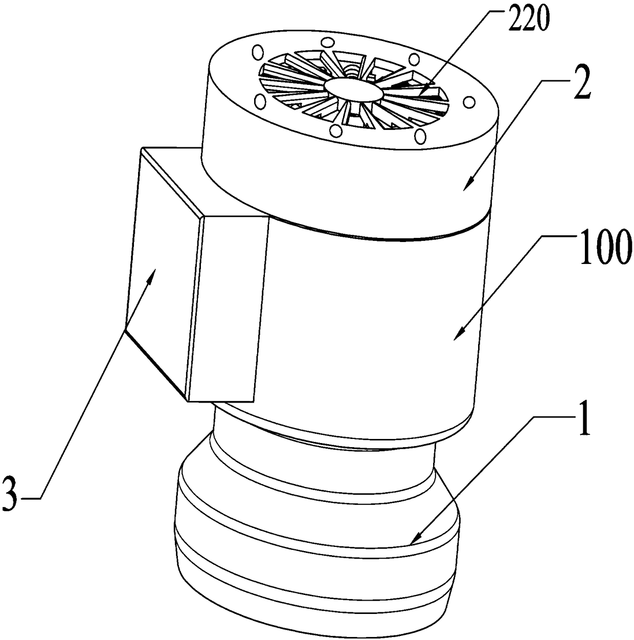
[0031] refer to Figure 1 to Figure 6 , the power system used in a large multi-rotor aircraft capable of precise speed regulation includes a fuselage 100, a turbine engine device 1, a motor device 2, a battery device 3 and an electric regulator 4, and the fuselage 100 is a hollow with open upper and lower ends. The cylinder, the motor device 2 and the turbine engine device 1 are respectively arranged at the upper and lower parts of the fuselage 100, and a battery box is arranged on the outer wall of the fuselage 100, and the battery device 3 and the electric regulator 4 are arranged in the battery box.

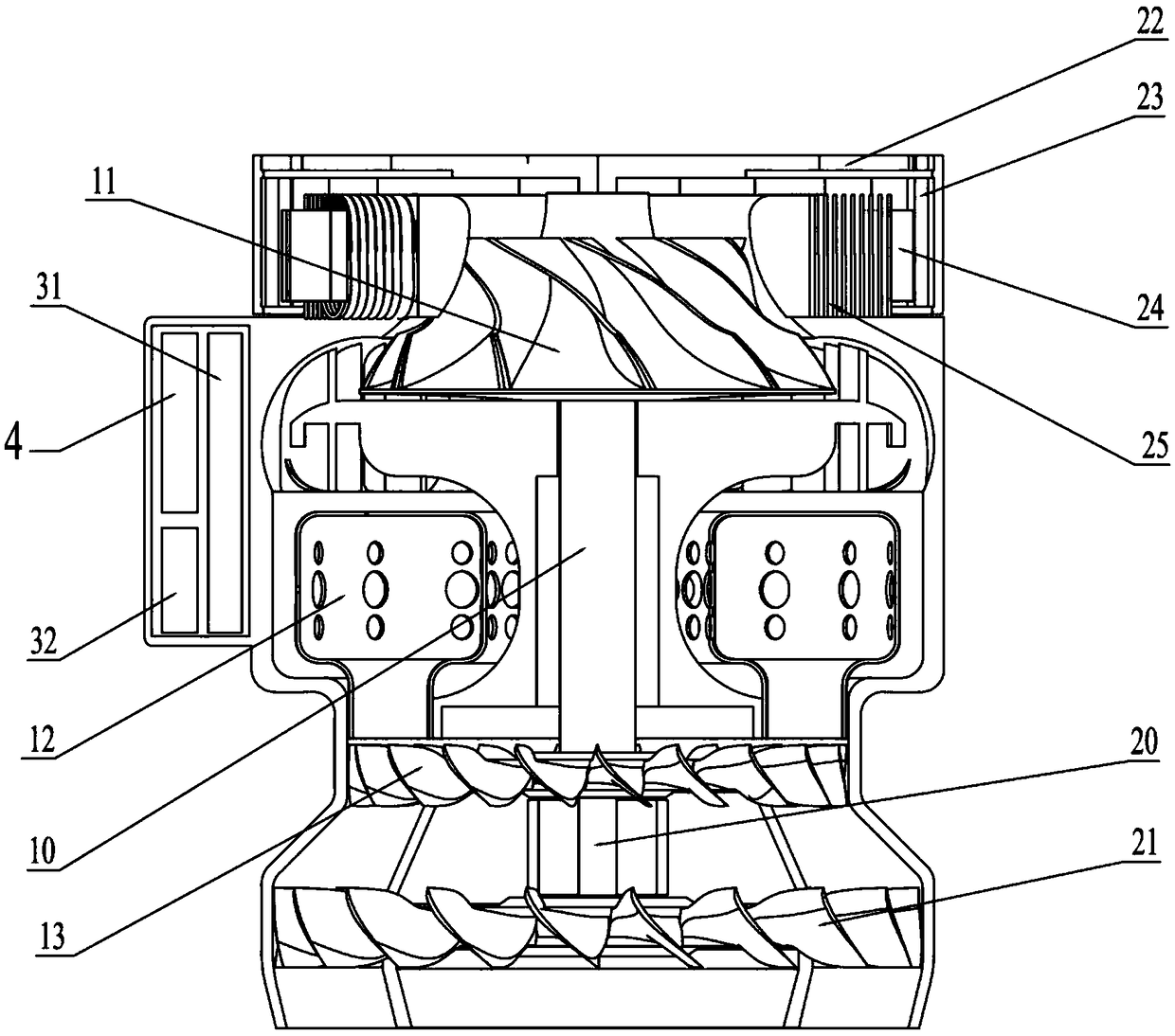
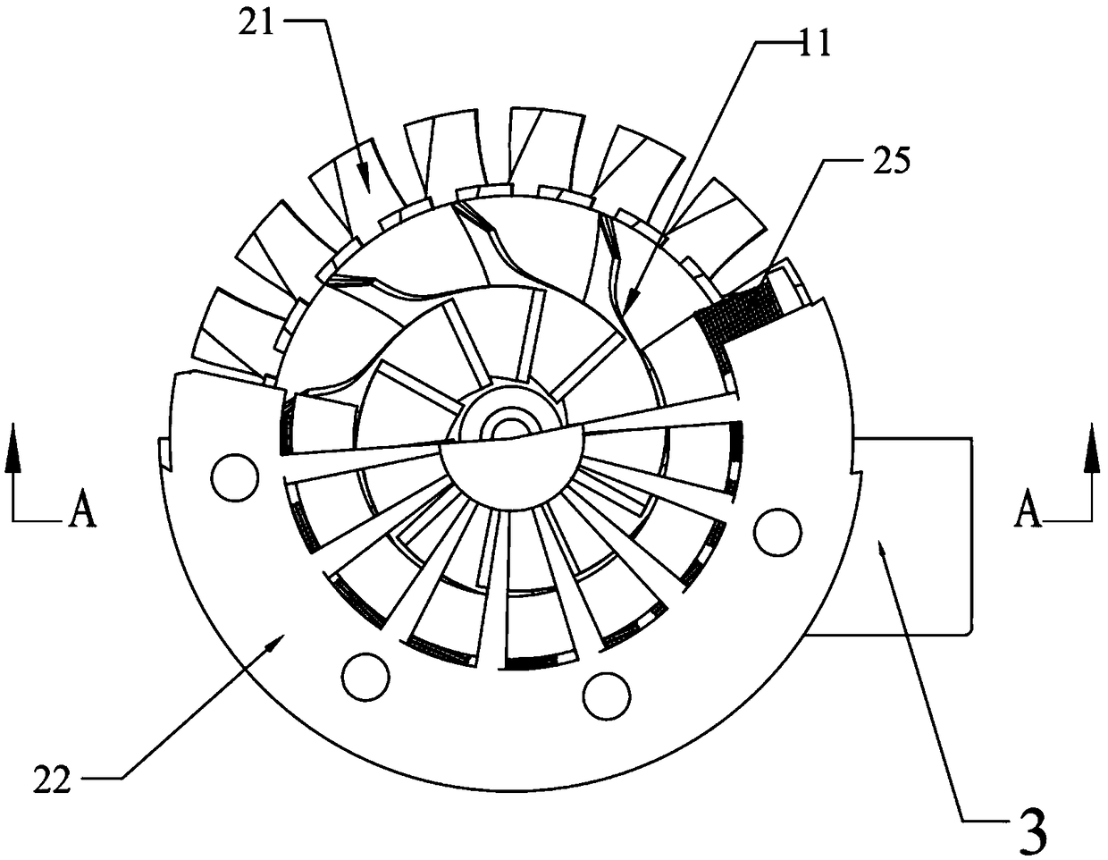
[0032]Further, the turbine engine device 1 includes a motor bushing 10 , a compressor 11 , a combustion chamber 12 and a turbine engine turbine 13 .

[0033] Wherein, the motor shaft sleeve 10 ...

Embodiment 2

[0047] On the structure of Example 1, this Example 2 has improved the power output mode, and the improved results are as follows:

[0048] refer to Figure 8 , the rotor end cover 22 is fixed on the upper end of the motor shaft 20, the middle part of the end face of the rotor end cover 22 is provided with a motor shaft hole, the motor shaft 20 is used as the power output end, the motor shaft 20 passes through the motor shaft hole to expose the top, the motor shaft 20 and the rotor The end covers 22 are connected by bearings, and the top end of the motor shaft 20 is fixed with a power output shaft 5 for connecting with the rotor shaft of a large multi-rotor aircraft.

Embodiment 3

[0050] On the structure of embodiment 1, this embodiment 3 has improved the power output mode, and the improved results are as follows:

[0051] A brushless DC motor is fixed on the rotor end cover 22, and the rotating shaft of the brushless DC motor is connected with the rotor shaft of a large multi-rotor aircraft. Wherein, the three-phase electric output end of the coil winding 25 is connected with the input end of the AC power converter which converts the AC into DC power through wires, and the output end of the AC power converter is connected with the input end of the brushless DC motor through wires.

[0052] First, the three-phase power of the coil winding 25 is converted into direct current; then, the direct current is input to the brushless DC motor; finally, the rotor shaft of the large multi-rotor aircraft is driven by the rotating shaft of the brushless DC motor to rotate to realize power output.


PUM


Abstract

The invention discloses a power system used in a large multi-rotor aircraft capable of precisely adjusting the speed, and relates to the technical field of multi-rotor aircrafts. The power system comprises a fuselage, a motor device on the upper portion of the fuselage, a turbine engine device on the lower portion of the fuselage, a battery device and an electronic speed controller, wherein the battery device and the electronic speed controller are arranged on the side wall of the fuselage. The motor device and the electronic speed controller as well as the electronic speed controller and thebattery device are connected through wires correspondingly. According to the power system, fuel oil with the high energy density is adopted, the structure of a turbojet engine is used for reference, the characteristic of rapid response in the battery energy transferring process is also given into full play, the problem of energy shortage of pure battery power supply is solved, fuselage vibration caused by motor rotation is eliminated, the defect of slow response in the process of energy transformation of an internal combustion engine is overcome, the contradiction between energy supply and precise speed adjusting in a power system of an existing multi-rotor aircraft is resolved, and large-scale development of the multi-rotor aircraft becomes possible.

Description

technical field [0001] The invention relates to the technical field of multi-rotor aircraft, in particular to a power system used in a large multi-rotor aircraft capable of precise speed regulation. Background technique [0002] A multi-rotor aircraft (such as helicopters and drones) is an aircraft with three or more rotors. Among them, the multi-rotor UAV includes a fuselage, a power system and a control system. It drives the rotation of multiple rotors on the fuselage through the rotation of the motor or engine in the power system. The lift force and the propulsion force of forward motion can be changed by changing the relative rotational speed between different rotors, so as to control the trajectory of the aircraft. The control system of the multi-rotor UAV adopts radio remote control, that is, it can still take off and land and hover autonomously without an operator driving, and is suitable for completing low-altitude, low-speed, vertical take-off and landing and hover...

Claims


Application Information

Patent Timeline
Patent Type & Authority Applications(China)
IPC IPC(8): B64D27/02B64D27/10B64D27/24H02K7/00H02K7/14
CPCB64D27/02B64D27/10B64D27/24B64D2027/026H02K7/00H02K7/14
Inventor 李江江
Owner 李江江
Why Eureka
Try Eureka