Method of blast furnace slag granulation and waste heat recovery
A waste heat recovery and blast furnace slag technology, applied in recycling technology, furnace, waste heat treatment and other directions, can solve the problems of reducing the particle size of granulated slag, low waste heat recovery efficiency, and large particle size of granulated slag, and achieves good fluidity, The effect of suppressing the formation of slag film
- Summary
- Abstract
- Description
- Claims
- Application Information
AI Technical Summary
Problems solved by technology
Method used
Image

Examples
Embodiment 1
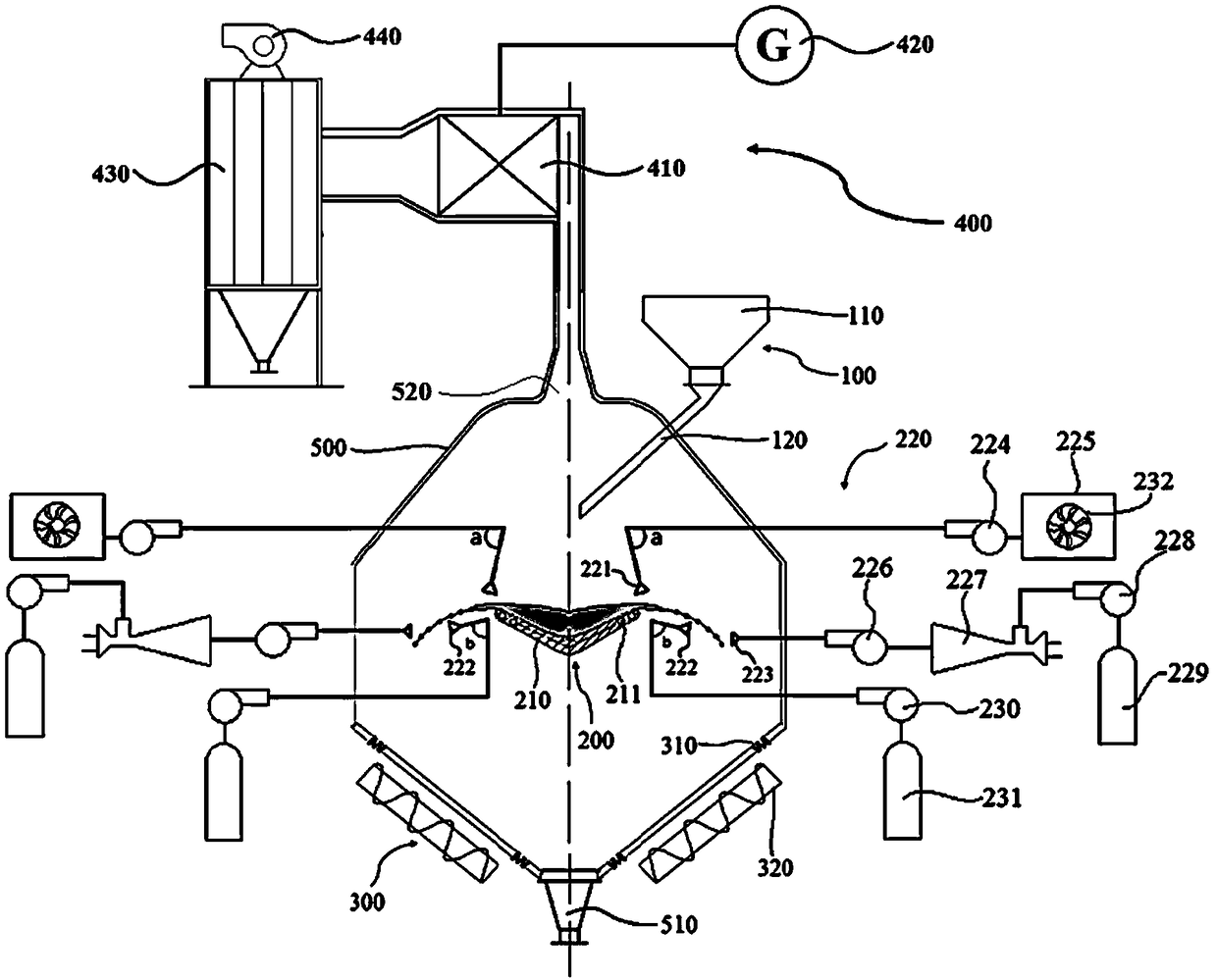
[0049] combine Figure 1~4 As shown in and 6, a method for blast furnace slag granulation and waste heat recovery in this embodiment, the blast furnace slag on the rotating slag pan 210 moves to the edge of the rotating slag pan 210 during the rotation, and the heating part of the rotating slag pan 210 211 heats and keeps the blast furnace slag; after the blast furnace slag leaves the rotating slag pan 210, the cooling mechanism 220 cools the blast furnace slag, and the cooled blast furnace slag forms granulated slag; the cooling water sprayed by the cooling mechanism 220 is heated and gasified by the blast furnace slag to form Water vapor, the water vapor enters the heat exchange unit 400 through the granulated slag outlet 510 , where the water vapor performs heat exchange treatment and waste heat utilization in the heat exchange unit 400 . Such as Image 6 As shown, the specific steps are:
[0050] Step 1: The blast furnace slag stored in the slag pot 110 flows into the ro...
Embodiment 2
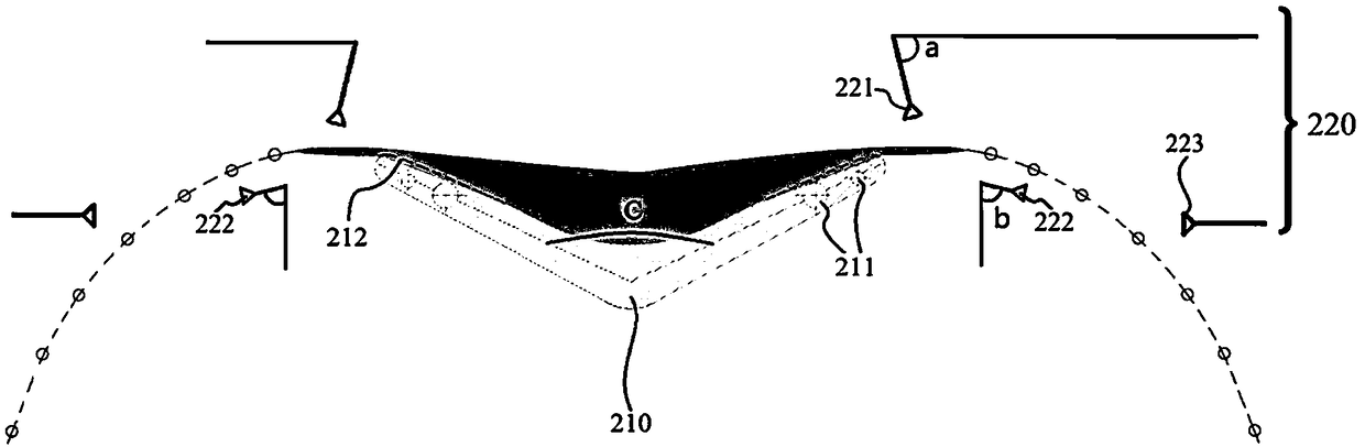
[0062]The basic content of this embodiment is the same as that of Embodiment 1, the difference is that: the slag nozzle 221 is arranged above the edge of the rotating slag pan 210. In this embodiment, there are 16 slag nozzles 221, and the slag nozzle 221 rotates along the The circumference above the edge of the slag pan 210 is uniformly distributed. In this embodiment, the slag nozzle 221 uses gas as a carrier to spray fine-grained slag to the edge of the rotating slag pan 210. The carrier for spraying granulated slag can also be other fluids such as water. The smaller granulated slag makes the granulated slag with a certain kinetic energy collide with the blast furnace slag at the edge of the rotating slag pan 210 to grow up. Secondary production and utilization of the granulated slag under resource utilization conditions; on the other hand, the slag film is broken through the impact of the smaller granulated slag and the air-based carrier, preventing the formed slag liquid ...
Embodiment 3
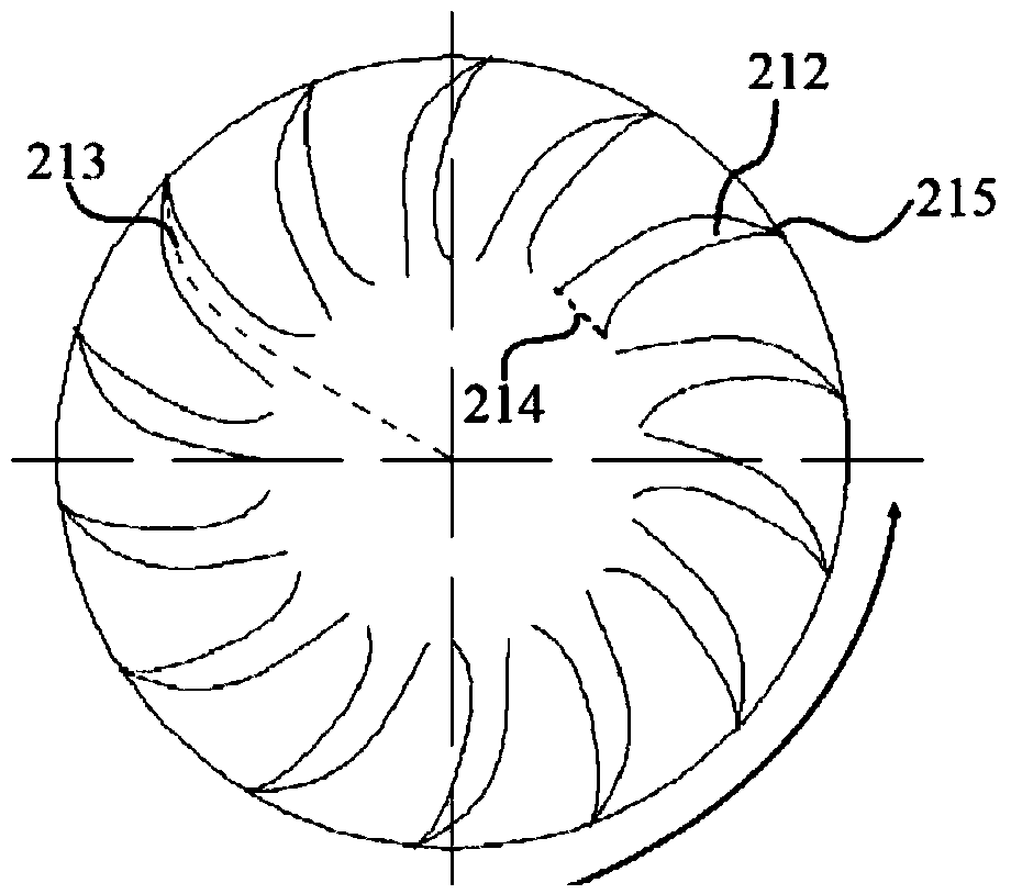
[0066] combine Figure 5 As shown, the basic content of this embodiment is the same as that of Embodiment 1, the difference is that: a raised surface 216 is provided between two adjacent slag troughs 212, and stoppers are provided at both ends of the circumferential edge of the raised surface 216. plate 217, so that the baffle plate 217 is located on both sides of the slag outlet of the slag flow tank 212, and the slag outlet of the slag flow tank 212 is the circumferential side 215. Its function is: the blast furnace slag located on the rotating slag pan 210 moves towards the edge of the rotating slag pan 210 under the action of centrifugal force, and part of the blast furnace slag flows out along the slag flow groove 212 through the slag outlet; On the convex surface 216, and then flow to the peripheral edge of the convex surface 216, when this part of the blast furnace slag moves to the peripheral edge position of the convex surface 216, it will be blocked by the baffle pla...
PUM
| Property | Measurement | Unit |
|---|---|---|
| particle size | aaaaa | aaaaa |
Abstract
Description
Claims
Application Information
 - R&D
- Intellectual Property
- Life Sciences
- Materials
- Tech Scout
- Unparalleled Data Quality
- Higher Quality Content
- 60% Fewer Hallucinations
Browse by: Latest US Patents, China's latest patents, Technical Efficacy Thesaurus, Application Domain, Technology Topic, Popular Technical Reports.
© 2025 PatSnap. All rights reserved.Legal|Privacy policy|Modern Slavery Act Transparency Statement|Sitemap|About US| Contact US: help@patsnap.com