Cell gas generation testing system

A test system and cell technology, which is applied in the direction of measuring electricity, measuring devices, measuring electrical variables, etc., can solve the problem of difficult to ensure the consistency and accurate test conditions of the battery cells, unable to characterize the gas production of the battery cells in situ, and the test results. Deviation from the actual value and other problems, to achieve the effect of qualitative and quantitative analysis, improve the gas production of the cell, and improve the service life

Inactive Publication Date: 2018-11-13
CONTEMPORARY AMPEREX TECH CO
View PDF11 Cites 6 Cited by
  • Summary
  • Abstract
  • Description
  • Claims
  • Application Information

AI Technical Summary

Problems solved by technology

[0004] However, the existing technology has the following problems: 1) The process of gas extraction and sample injection is easily disturbed by the air, causing the test results to deviate from the actual value; 2) When the battery cell produces too little gas, the GC gas needle can hardly extract gas Or most of the extracted gas is air, so effective data cannot be obtained; 3) It is impossible to characterize the gas production of the battery in each stage in situ. Taking the overcharge of the battery as an example, if you want to analyze the overcharge of the battery For the gas production behavior in the process, it is necessary to take a large number of batteries of the same design, charge each battery cell to a different SOC, and then conduct a GC test on the gas production of each battery cell, and then correlate the change of gas production with SOC , the above method is difficult to ensure the consistency of the cell and accurate test conditions

Method used


Image

  • Cell gas generation testing system
  • Cell gas generation testing system
  • Cell gas generation testing system

Examples


Embodiment Construction

[0039] In order to make the purpose of the invention, the technical solution and its beneficial technical effects clearer, the present invention will be further described in detail below in conjunction with the accompanying drawings and specific embodiments. It should be understood that the specific implementations described in this specification are only for explaining the present invention, not for limiting the present invention.

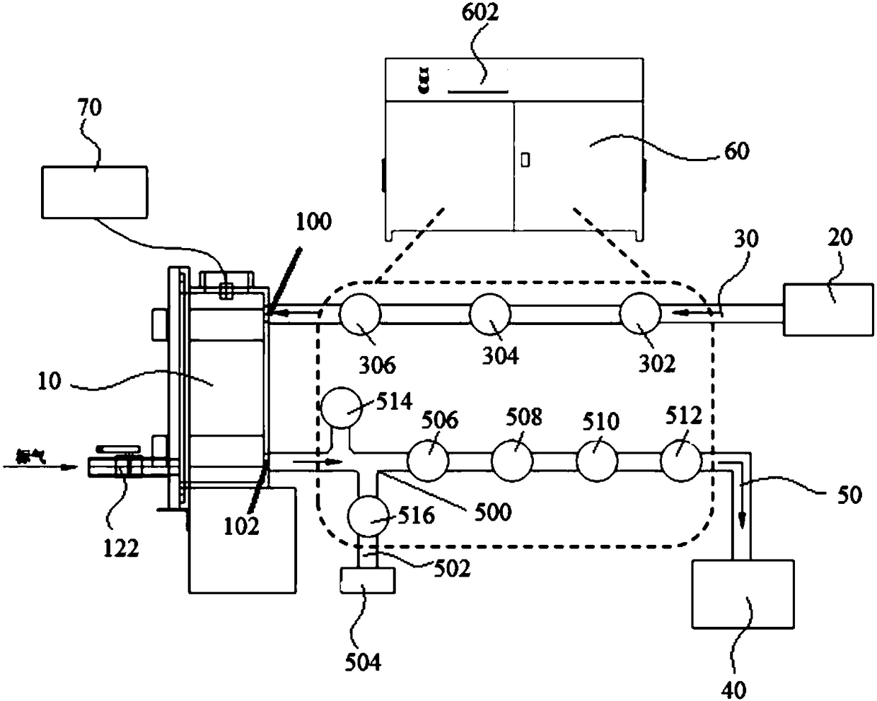
[0040] see figure 1 As shown, the cell gas production test system of the present invention includes:

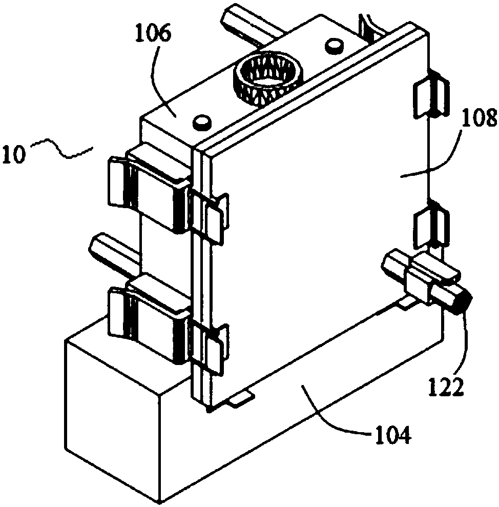
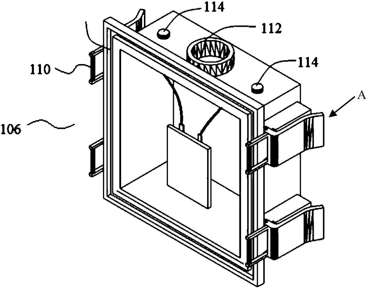
[0041] Sealed test box 10, used to accommodate batteries (not shown), which is provided with an air inlet 100 and an air outlet 102;

[0042] An inert gas source 20 is connected to the air inlet 100 through an air inlet pipeline 30; and

[0043] The analysis device 40 is connected with the gas outlet 102 through the gas outlet pipeline 50;

[0044] Wherein, the outlet pipeline 50 is provided with an interface 500, the interface 500 is connecte...


PUM


Abstract

The invention discloses a cell gas generation testing system. The system comprises a sealed testing box, an inert gas source and an analyzing device and is characterized in that the sealed testing boxis used for accommodating a cell and is provided with a gas inlet and a gas outlet; the inert gas source is connected with the gas inlet through a gas inlet pipeline; the analyzing device is connected with the gas outlet through a gas outlet pipeline, the gas outlet pipeline is provided with a connector, and the connector is connected with a vacuum pump through a first pipeline. Compared with theprior art, the system has the advantages that the gas generation behavior of the cell at every moment can be monitored, and high testing precision is achieved; the analyzing device is used to analyzethe components and content of the gas generated by the cell, so that qualitative and quantitative analysis of cell gas generation is achieved; the cell is located in the inert atmosphere in the wholegas generation testing to avoid the risks of accidents.

Description

technical field [0001] The invention belongs to the field of battery technology, and more specifically, the invention relates to a battery cell gas production test system. Background technique [0002] Lithium-ion batteries will produce gas during the process of production and use. The mechanism of battery gas production caused by different reasons is different, and the gas production components and the proportions of each component are different, and for the battery gas production caused by the same reason, the gas production components and The proportion will also vary depending on the material, electrolyte formulation and usage environment. Taking chemical gas production as an example, ethylene carbonate, propylene carbonate and ethyl methyl carbonate produce different gases during the chemical conversion process. In addition, during the storage process of the battery, the gas production components are different with the change of the state of charge (SOC) of the batter...

Claims


Application Information

Patent Timeline
IPC IPC(8): G01N33/00G01R31/36
CPCG01N33/00G01N33/0004
Inventor 黄婷魏奕民戴璐王益李迎娇
Owner CONTEMPORARY AMPEREX TECH CO
Why Eureka
Try Eureka