
A Prediction Method of Point Contour Error on Part Side Milling Surface

A technology of contour error and prediction method, which is applied in the direction of program control, instrument, computer control, etc., and can solve the problems of inaccurate prediction results and less research

Active Publication Date: 2021-01-29
SOUTHWEST JIAOTONG UNIV
View PDF6 Cites 0 Cited by
  • Summary
  • Abstract
  • Description
  • Claims
  • Application Information

AI Technical Summary

Problems solved by technology

[0003] However, in some precision machining processes, it is not only necessary to measure the profile error after machining, but also to predict the point profile error of the surface before machining, so as to analyze and compensate the process accuracy; There are few studies on contour error prediction, such as Zhu Shaowei (Zhu Shaowei. Research on precision prediction and compensation technology for five-axis milling of complex parts [D]. Chengdu: Southwest Jiaotong University, 2013.) Using the comprehensive error model of five-axis machine tools to calculate the prediction points Projected to the normal direction of the part contour; obtained point contour error, and analyzed the proportion of each error factor; Peng Lian et al. China Mechanical Engineering, 2014, 25(5): 647-650.) Using the five-axis milling precision prediction software system developed by the research and development, the contour error at the cutting point is calculated; The projection of the spatial position error on the normal direction is regarded as the point contour error; however, in the actual measurement process, the probe of the three-coordinate measuring machine approaches the actual surface along the normal direction of the ideal measuring point, and finally the probe touches an actual measuring point on the actual surface , and then calculate the distance between the actual measuring point and the ideal measuring point, which is the point contour error value of the ideal measuring point
Therefore, there is a deviation between the actual measured value and the predicted value of the aforementioned forecasting method, resulting in inaccurate forecasting results

Method used


Image

  • A Prediction Method of Point Contour Error on Part Side Milling Surface
  • A Prediction Method of Point Contour Error on Part Side Milling Surface
  • A Prediction Method of Point Contour Error on Part Side Milling Surface

Examples


Embodiment

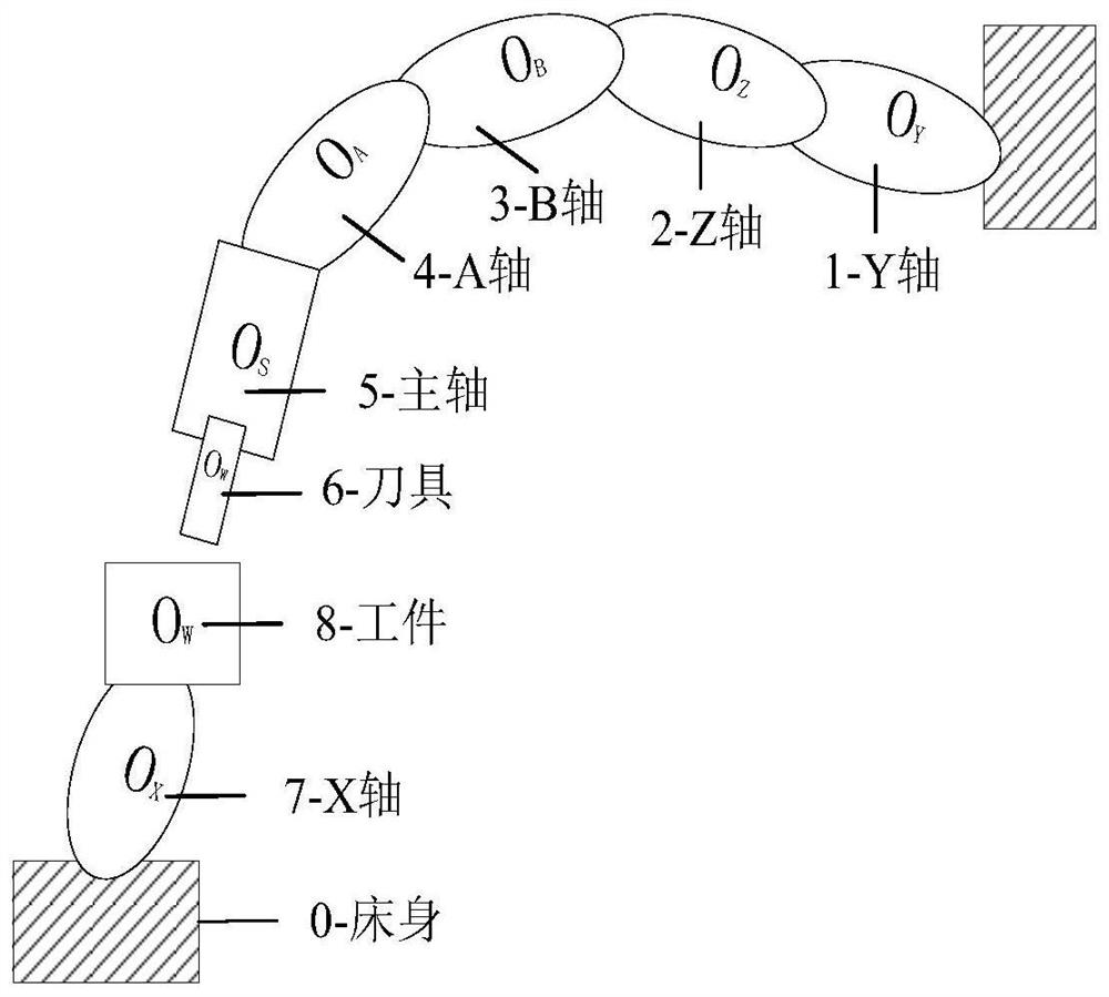
[0115] Taking the XFYZBA structure machine tool to process an "S" shape with a wall thickness of 3mm as an example, the validity of the accuracy prediction algorithm is verified; the tool contact distribution of the local tool sweep surface is calculated, and part of the tool contacts 15 (along the tool axis Select 15 layers in the feed direction) × 20 (select 20 columns along the milling feed direction) = 300, the prediction results are as follows Figure 6 shown.

[0116] The result is as Figure 7 It can be seen from the figure that the predicted value has the same trend as the measured value, which verifies the validity of the prediction algorithm.

[0117] The present invention firstly calculates the ideal and actual tool contacts of side milling under multi-error conditions; then uses the method of surface fitting to obtain the parametric calculation models of the ideal and actual machining surfaces of the parts; according to the principle of contour error measurement, ...


PUM


Abstract

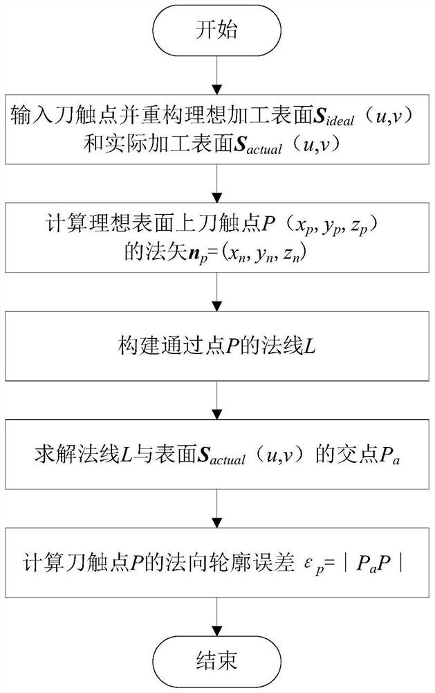
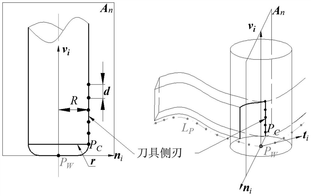
The invention discloses a point position contour error prediction method on the side milling surface of a part. Step 1: Obtain the ideal tool position point in the prediction area, and obtain the corresponding actual tool position point according to the multi-body theory and homogeneous coordinate transformation; Step 2: Select several points on the side edge of the tool as the knife contact, and calculate the ideal knife contact corresponding to the ideal knife position and the actual knife contact corresponding to the actual knife position according to the geometric relationship between the knife position point and the knife contact point; step 3: According to the ideal knife contact and the actual knife contact obtained in step 2, construct the ideal machining surface S i and the actual machined surface S a ;Step 4: Calculate the predicted points on the ideal machined surface obtained through step 3 P The intersection of the normal and the actual machined surface P a ;Calculate prediction points P and intersection P a distance to get the predicted point P point contour error at the position; the measurement and evaluation principle of the present invention is consistent with the contour measurement method, and the prediction is more accurate.

Description

technical field [0001] The invention relates to the technical field of numerical control machining, in particular to a method for predicting and calculating point contours on the side milling surface of a part. Background technique [0002] Side milling refers to the processing method of milling the workpiece with the side edge of the milling cutter. It is often used in the processing of ruled surface parts and is an important numerical control processing method; One of the widely used evaluation indicators; at present, the measurement and calculation methods of contour error are relatively mature, and commonly used calculation methods include iterative algorithm, genetic algorithm, etc.; such as Sun et al. (SUN Y, WANG X, GUO D.Machining localization and qualityevaluation of parts with sculpted surfaces using SQP method[J].International Journal of Advanced Manufacturing Technology,2009,42(11-12):1131-1139.) proposed a sequence quadratic programming algorithm (SQP) to solve ...

Claims


Application Information

Patent Timeline
Patent Type & Authority Patents(China)
IPC IPC(8): G05B19/404
CPCG05B19/404G05B2219/35408
Inventor 丁国富江磊余杭卓罗豪张剑马术文
Owner SOUTHWEST JIAOTONG UNIV
Learn More