
Thrombus aspiration catheter with spiral cutting bolt breaking function

A suction catheter and spiral technology, applied in the field of medical devices, can solve the problems of prolonging the recovery time of patients, blocking the vascular cavity, and excessive agitation of blood vessels, and achieve the effects of reducing surgical complications, improving safety, and being convenient to use

Inactive Publication Date: 2018-11-16
昆山金泰医疗科技有限公司
View PDF9 Cites 3 Cited by
  • Summary
  • Abstract
  • Description
  • Claims
  • Application Information

AI Technical Summary

Problems solved by technology

[0002] Embolism refers to the phenomenon that abnormal substances insoluble in blood appear in the circulating blood and block the vascular lumen along with the blood flow. At present, thrombus suction devices are usually used to treat it. However, the existing thrombus suction systems, some are By passing high-pressure heparin saline into the catheter, Bernoulli’s principle is used to generate negative pressure to break up and extract the thrombus. In this way, because the suction time is relatively long, it will cause excessive blood loss or hematuria, thereby prolonging the patient’s life. Recovery time; there are also systems that use the high-speed rotating catheter head and the long coil inside the catheter to generate cutting action and negative pressure (generally 43.5mmHg) through high-speed (generally 40,000 revolutions per minute) movement left and right), so that the cut thrombus debris is transported by the coil to the waste liquid collection bag at the active device. In this way, because the catheter head exposed to the blood rotates at high speed, it will cause excessive agitation in the blood vessel, thus cause unavoidable complications

Method used


Image

  • Thrombus aspiration catheter with spiral cutting bolt breaking function
  • Thrombus aspiration catheter with spiral cutting bolt breaking function
  • Thrombus aspiration catheter with spiral cutting bolt breaking function

Examples


Embodiment Construction

[0023] In order to make the purpose, technical solutions and advantages of the embodiments of the present invention clearer, the technical solutions in the embodiments of the present invention will be clearly and completely described below in conjunction with the accompanying drawings in the embodiments of the present invention. Obviously, the described embodiments It is some embodiments of the present invention, but not all of them. The components of the embodiments of the invention generally described and illustrated in the figures herein may be arranged and designed in a variety of different configurations.

[0024] Accordingly, the following detailed description of the embodiments of the invention provided in the accompanying drawings is not intended to limit the scope of the claimed invention, but merely represents selected embodiments of the invention. Based on the implementation manners in the present invention, all other implementation manners obtained by persons of or...


PUM


Abstract

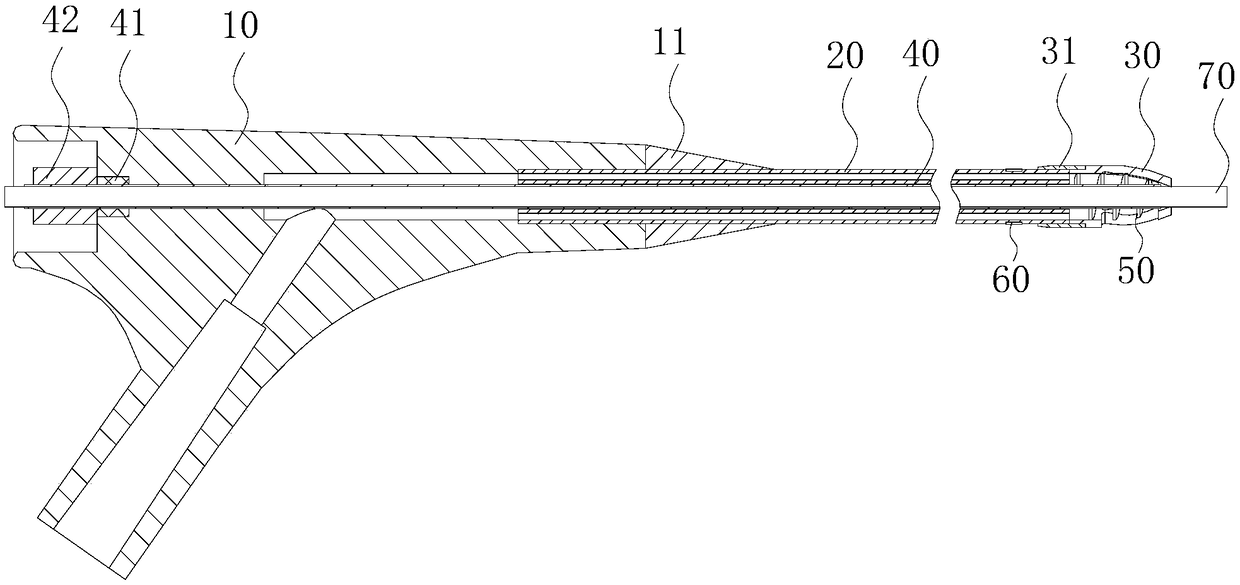
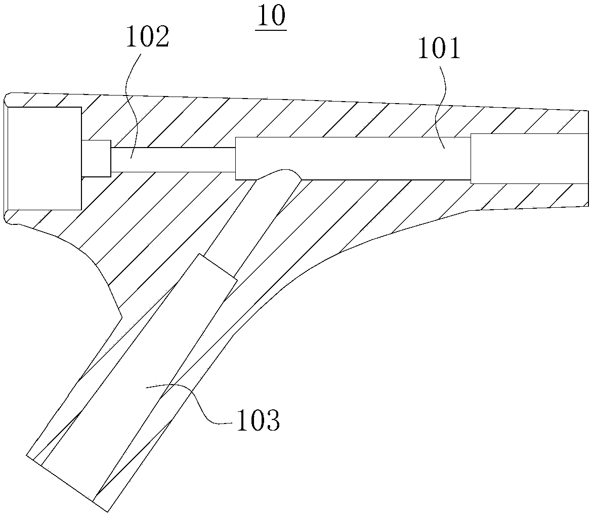
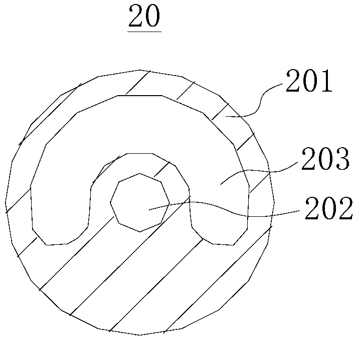
The invention discloses a thrombus aspiration catheter with the spiral cutting bolt breaking function, and belongs to the technical field of medical apparatus and instruments. The catheter comprises apipe base, a double-cavity pipe, a protective shell, a transmission pipe and a cutting tool; the pipe base is provided with a first connecting end, a second connecting end and a third connecting end,a blind hole is formed in the first connecting end of the pipe base, a pipe hole is formed in the bottom of the blind hole, and a diversion hole is formed in the third connecting end of the pipe base; the double-cavity pipe comprises a pipe body which is internally provided with a first channel and a second channel, one end of the pipe body is inserted into the blind hole, the axis of the first channel coincides with the axis of the pipe hole, the second channel is communicated with the diversion hole, the protective shell is arranged at the end, away from the pipe base, of the pipe body, a through hole is formed in the side wall of the protective shell, a transmission pipe penetrates through the pipe hole and the first channel, one end of the transmission pipe extends into the protectiveshell, and a cutting tool is arranged at the end, located in the protective shell, of the transmission pipe. Accordingly, the structure is simple, convenience is brought to use, the safety is good, and operative complications can be greatly lowered.

Description

technical field [0001] The invention belongs to the technical field of medical devices, and in particular relates to a thrombus suction catheter with the function of spirally cutting thrombus. Background technique [0002] Embolism refers to the phenomenon that abnormal substances insoluble in blood appear in the circulating blood and block the vascular lumen along with the blood flow. At present, thrombus suction devices are usually used to treat it. However, the existing thrombus suction systems, some are By passing high-pressure heparin saline into the catheter, Bernoulli’s principle is used to generate negative pressure to break up and extract the thrombus. In this way, because the suction time is relatively long, it will cause excessive blood loss or hematuria, thereby prolonging the patient’s life. Recovery time; there are also systems that use the high-speed rotating catheter head and the long coil inside the catheter to generate cutting action and negative pressure (...

Claims


Application Information

Patent Timeline
IPC IPC(8): A61B17/22
CPCA61B17/22012A61B2017/22079
Inventor 孙家茂王泱杨青林
Owner 昆山金泰医疗科技有限公司
Learn More