A dust collector for a plastic spraying machine

A recycling device and plastic spraying machine technology, applied in the direction of injection devices, etc., can solve the problems of complex structure, loud noise, slow plastic powder falling, etc., and achieve the effect of good recycling effect, low noise and low power consumption

Active Publication Date: 2021-07-16
SUZHOU ZHONGKUANG SANJIE TECH
View PDF7 Cites 0 Cited by
  • Summary
  • Abstract
  • Description
  • Claims
  • Application Information

AI Technical Summary

Problems solved by technology

In the process of use, we found that the structure of the plastic powder recycling unit has too many motors, complex structure, loud noise, slow plastic powder falling, easy to leak after long-term use, and difficult to recycle.

Method used


Image

  • A dust collector for a plastic spraying machine
  • A dust collector for a plastic spraying machine
  • A dust collector for a plastic spraying machine

Examples


Embodiment 1

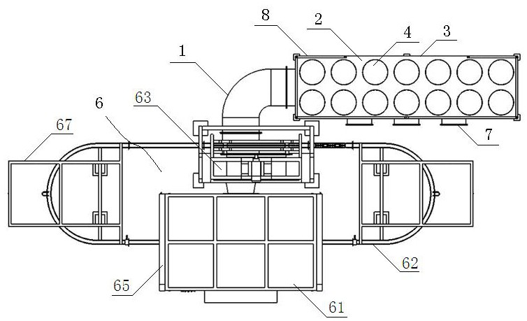
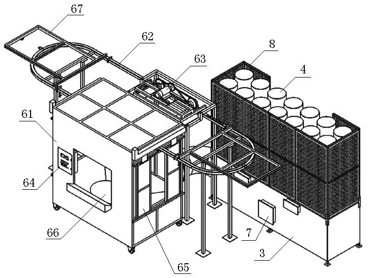
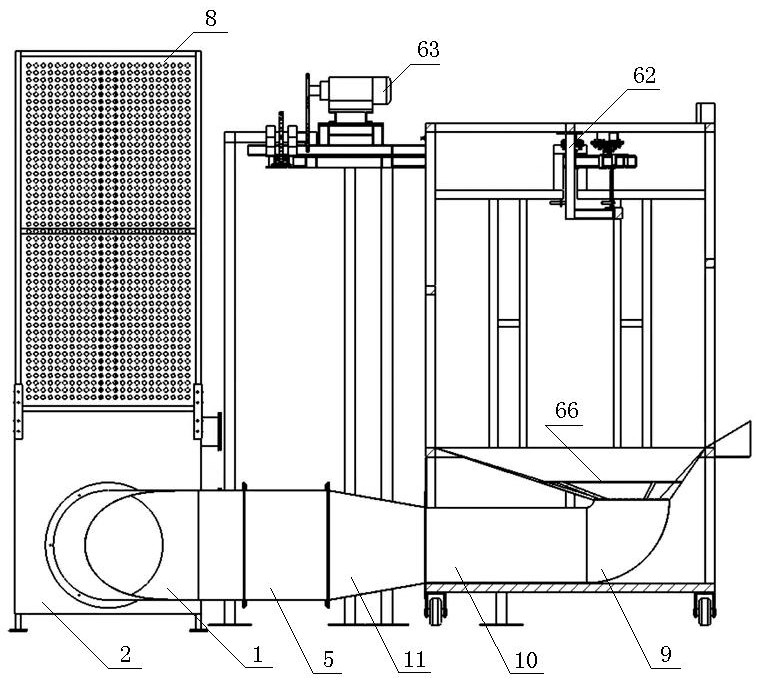
[0023] A dust suction recovery device for a plastic spraying machine, comprising a connecting pipe 1 and a recovery mechanism 2, the recovery mechanism 2 comprising a recovery box 3 and several dust suppression cylinders 4 installed on the recovery box, the dust suppression cylinders 4 are closed at one end and open at the other end The same hollow cylinder as the opening of the dust reduction tube is set on the top plate of the recovery box 3, the opening end of the dust suppression tube is installed on the opening of the recovery box, the powder pulling fan 5 is installed in the middle of the connecting pipe 1, and one end of the connecting pipe 1 is connected to the Plastic powder diffusion unit 6, the other end is connected to recovery box 3.

Embodiment 2

[0025] As a kind of preference of embodiment 1, partition board is set in the middle of described recovery box 3, and partition board divides recovery box into lower recovery box, upper recovery box, and partition board is provided with recovery box opening at the same position as top plate, and described dust-reducing tube 4 At least two layers of cylinders are included, the bottom of the outer cylinder is installed on the opening of the outer surface recovery box on the top of the upper recovery box, the bottom of the inner cylinder is installed on the outer surface of the top of the lower recovery box and is located in the box of the upper recovery box, The inner cylinder is a hollow cylinder, and the wall of the outer cylinder and the inner cylinder are hollow.

Embodiment 3

[0027] As a preference of Embodiment 2, several through holes are provided on the wall of the inner cylinder, and the through holes connect the inner cylinder and the space between the inner cylinder and the outer cylinder.

[0028] There are an even number of the dust suppression cylinders 4 .

[0029] The dust suppression tube 4 is configured as a cylinder, and the box body is a cuboid.

[0030] On the recovery box 3, a recovery opening is set, and a recovery opening door 7 is installed on the recovery opening, one is set on the lower recovery box, and two are set on the upper recovery box.

[0031] Protective mesh panels 8 are arranged on the four sides of the box body of the recovery box 3 .


PUM


Abstract

The invention discloses a dust suction recovery device for a plastic spraying machine, which comprises a connecting pipe and a recovery mechanism. The recovery mechanism comprises a recovery box and a plurality of dust-reducing cylinders installed on the recovery box. The cylinder body and the top plate of the recovery box are provided with the same opening of the recovery box as the opening of the dust reduction tube. The opening end of the dust suppression tube is installed on the opening of the recovery box. One end connects to a recycling bin. The structure of the air pressure plate and the connecting pipe set in the anti-plastic powder diffusion unit of the present invention minimizes the influence of the powder pulling fan on the plastic spraying work, and at the same time, can completely suck the plastic powder into the recycling box, which has a great impact on the plastic spraying. There is no health impact on the operator; the recovery box has fast dust reduction, no leakage, and good recovery effect. Only one powder pulling fan is used, with low power consumption and low noise.

Description

technical field [0001] The invention relates to a dust collection recovery device for a plastic spraying machine, which belongs to the technical field of spraying equipment. Background technique [0002] At present, the antirust and decoration measures for workpieces mainly include three forms: adding coating, spraying paint, and spraying plastic. Among them, the process of adding coating is complicated, the use of chemicals is very large, and the cost of sewage treatment in the later stage is extremely high, which greatly increases the manufacturing cost of the product. Spraying paint generally needs to be sprayed with primer first and then with topcoat three times, and the mist powder produced by spraying paint is difficult to collect, which has caused great pollution to the environment. Compared with these two anti-rust and decorative measures, spraying is much more convenient. [0003] There are two main types of existing plastic spraying equipment. One is low-end plas...

Claims


Application Information

Patent Timeline
Patent Type & Authority Patents(China)
IPC IPC(8): B05B14/10
CPCB05B14/10Y02P70/10
Inventor 王勇张迎春纪俊章马彬王万纪蒲申申薛勇季素音陆化阮辉周阳
Owner SUZHOU ZHONGKUANG SANJIE TECH
Why Eureka
Try Eureka