
Novel environment-friendly electric ceramic tile cutter

A cutting machine and electric technology, which is applied in the field of new environmentally friendly electric tile cutting machines, can solve the problems of time-consuming, laborious, poor flexibility, and inconvenient loading and unloading, and achieve the effects of improving safety, improving work efficiency, and facilitating loading and unloading work

Pending Publication Date: 2018-11-16
浙江润土城乡规划设计有限公司
View PDF5 Cites 1 Cited by
  • Summary
  • Abstract
  • Description
  • Claims
  • Application Information

AI Technical Summary

Problems solved by technology

[0002] In the prior art: the patent with the authorized publication number of CN 206998563 U discloses a new type of environmentally friendly electric tile cutter, including a water tank and a workbench, the water tank and the workbench are directly connected to form an integrated structure, and the top of the workbench A casing is connected, a water pump is arranged inside the casing, a bearing is connected to the top of the water pump, and a beam is connected to the top of the bearing, a water pipe is connected to the bottom of the water pump, and a one-way valve is arranged on the water pipe, and The other side of the water pipe is connected to a hydraulic cylinder, the top of the hydraulic cylinder is connected to a piston, and a throttle valve is arranged on one side of the hydraulic cylinder, and a counterweight beam is connected to one side of the beam, and the end of the counterweight beam is connected to There is a counterweight boom, and the top of the counterweight boom is connected with a counterweight iron, which has poor flexibility, inconvenient loading and unloading, and time-consuming and laborious

Method used


Image

  • Novel environment-friendly electric ceramic tile cutter
  • Novel environment-friendly electric ceramic tile cutter

Examples


Embodiment Construction

[0039] The following will clearly and completely describe the technical solutions in the embodiments of the present invention with reference to the accompanying drawings in the embodiments of the present invention. Obviously, the described embodiments are only some, not all, embodiments of the present invention. Based on the embodiments of the present invention, all other embodiments obtained by persons of ordinary skill in the art without making creative efforts belong to the protection scope of the present invention.

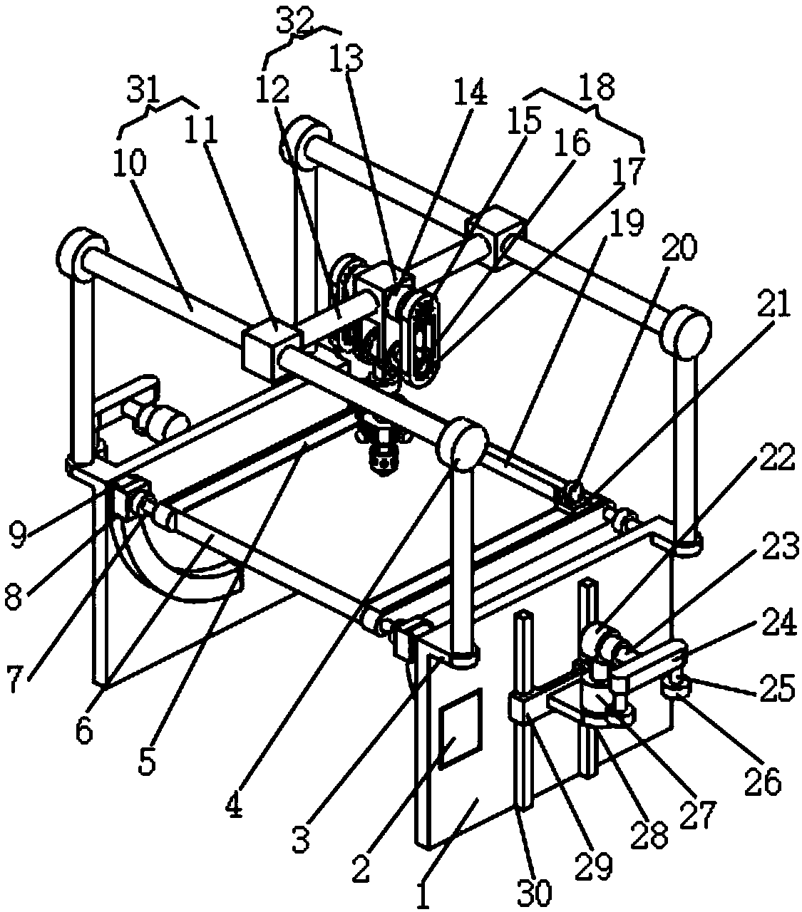
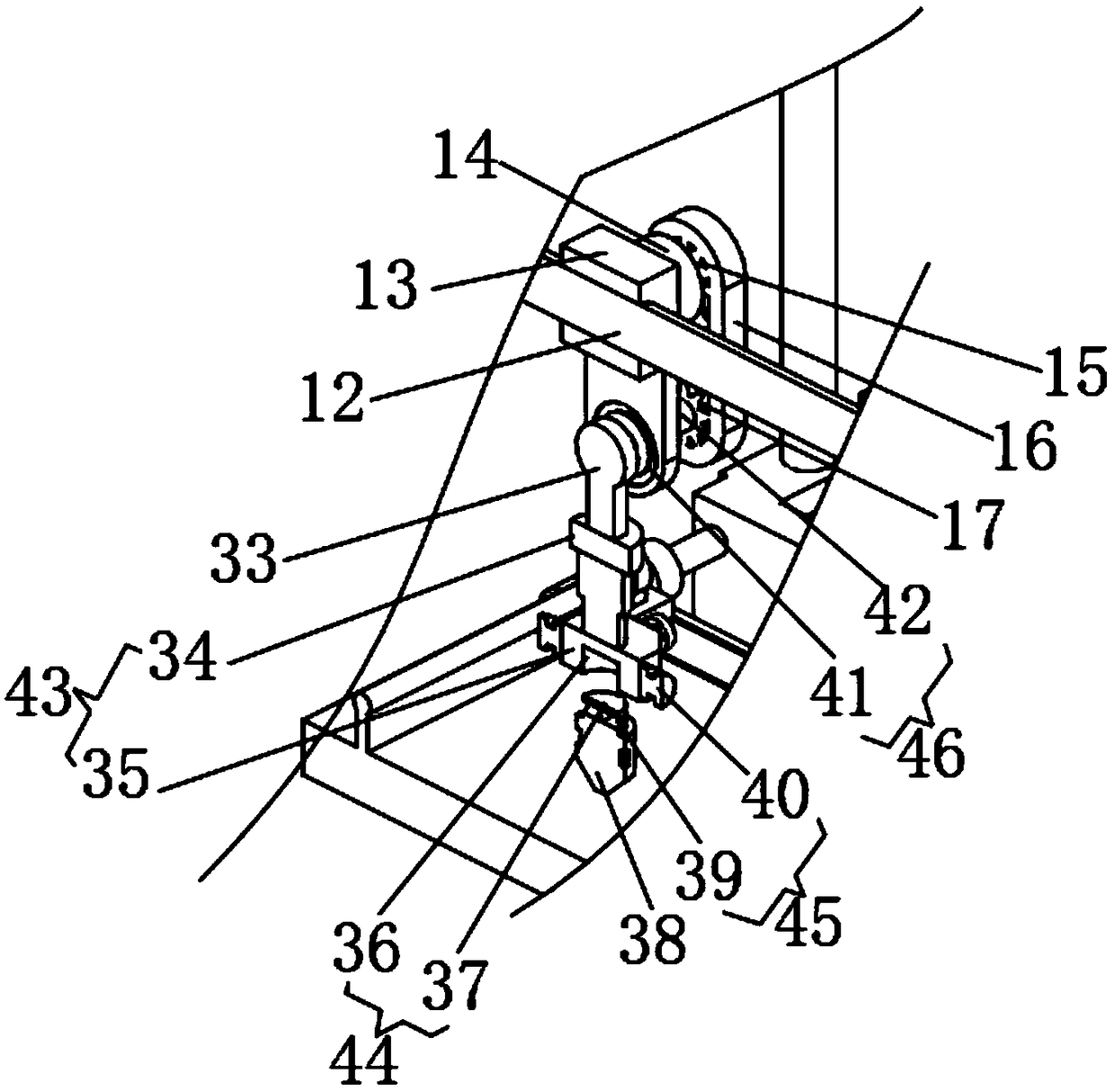
[0040] see Figure 1-2 , the present invention provides a technical solution: a novel environment-friendly electric ceramic tile cutting machine, comprising a base plate (1), two sets of base plates (1), and two sets of base plates (1) arranged symmetrically from left to right;

[0041] The base plate (1) is hinged with a cutting platform (6) through a rotary hinge;

[0042] The inner side of the base plate (1) is fixed with an arc-shaped guide rail (9);

[...


PUM


Abstract

The invention discloses a novel environment-friendly electric ceramic tile cutter which comprises two base plates which are symmetrically arranged left and right. The base plates are hinged to a cutting platform through rotary hinges; an arc-shaped guide rail is fixed to the inner side of each base plate; a first linear motor is movably hinged to each arc-shaped guide rail; the first linear motoris rotatably connected to the cutting platform through a rotary connecting part; a horizontal guide rail is fixed to the top of the cutting platform; a second linear motor is movably connected to thehorizontal guide rail; a row brush is fixed to the side face of the second linear motor; and brush hairs of the row brush are in contact with the table board of the cutting platform. According to thenovel environment-friendly electric ceramic tile cutter disclosed by the invention, an electric vacuum sucking disc is controlled by means of a control switch to adsorb and fix ceramic tiles, and a third linear motor is controlled by means of the control switch to more linearly on a vertical guide rail, so that the working height of the electric vacuum sucking disc is adjusted.

Description

technical field [0001] The invention relates to the technical field of tile processing equipment, in particular to a novel environment-friendly electric tile cutter. Background technique [0002] In the prior art: the patent with the authorized publication number of CN 206998563 U discloses a new type of environmentally friendly electric tile cutter, including a water tank and a workbench, the water tank and the workbench are directly connected to form an integrated structure, and the top of the workbench A casing is connected, a water pump is arranged inside the casing, a bearing is connected to the top of the water pump, and a beam is connected to the top of the bearing, a water pipe is connected to the bottom of the water pump, and a one-way valve is arranged on the water pipe, and The other side of the water pipe is connected to a hydraulic cylinder, the top of the hydraulic cylinder is connected to a piston, and a throttle valve is arranged on one side of the hydraulic ...

Claims


Application Information

Patent Timeline
IPC IPC(8): B28D1/22B28D7/04B28D7/00
CPCB28D1/22B28D7/00B28D7/043B28D7/046
Inventor 胡宝林
Owner 浙江润土城乡规划设计有限公司
Learn More