Iron concentrate storage and transportation system

A technology for iron ore concentrate and concentrate, which is applied in the directions of transportation and packaging, loading/unloading, conveyors, etc., can solve the problem of increasing the energy consumption of pelletizing or sintering operations, increasing the consumption of loading machinery and manpower, and reducing the effective storage of ore piles. Mineral volume and other issues, to achieve the effect of reducing maintenance costs and labor costs, improving loading efficiency, and high loading efficiency

Pending Publication Date: 2018-11-16
中冶北方(大连)工程技术有限公司
View PDF0 Cites 0 Cited by
  • Summary
  • Abstract
  • Description
  • Claims
  • Application Information

AI Technical Summary

Problems solved by technology

When the ore pile is used for storage, in order to prevent the blockage of the discharge port, the general ore pile has no more than three discharge ports, in case there are too many discharge ports, and a single discharge port does not work for a long time, resulting in mineral hardening and blockage. The material opening, and too few discharge openings greatly reduce the effective volume of the entire ore heap, reducing the effective ore storage capacity of the ore heap
In order to prevent blockage and increase the effective volume of ore piles, many mines, especially mines transported by rail, adopt front-loading machine loading. However, the way of front-loading machine loading has problems such as excessive loading machinery and manpower consumption, and high loading costs. Moreover, in order to facilitate the entrance and exit of the front-loading machine, most of this method does not have a roof, so that the iron concentrate will be wet in rainy days, thereby greatly increasing the moisture content of the iron concentrate powder and increasing the energy consumption of subsequent pelletizing or sintering operations.

Method used


Image

  • Iron concentrate storage and transportation system
  • Iron concentrate storage and transportation system

Examples


Embodiment Construction

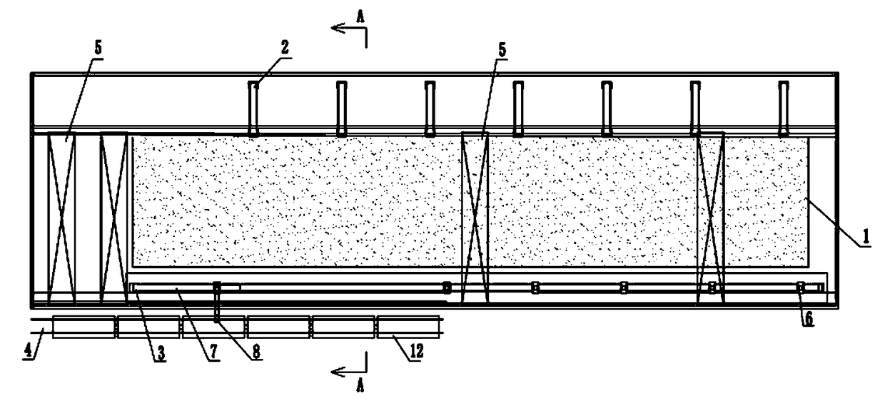
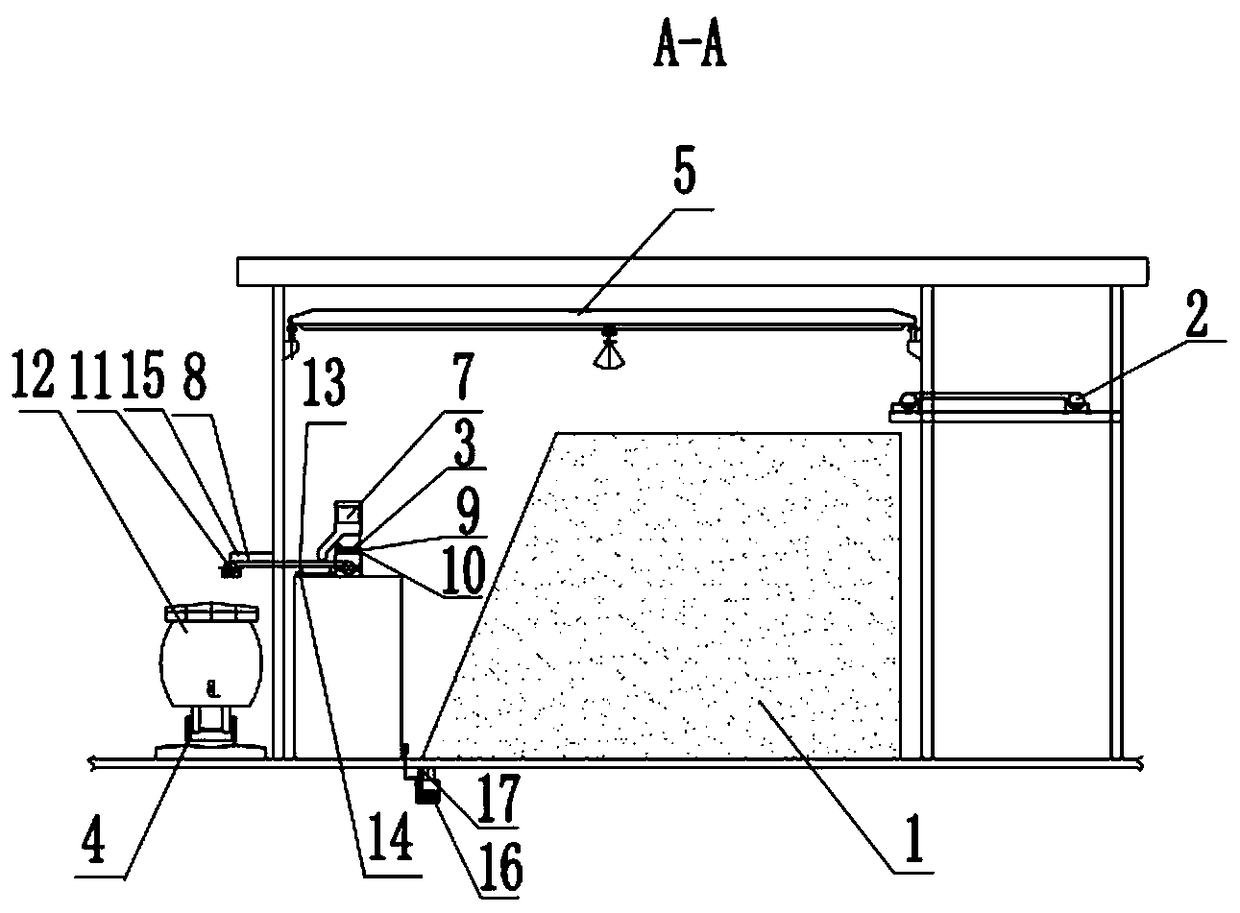
[0021] The specific implementation manner of the present invention will be further described below in conjunction with the accompanying drawings.

[0022] like figure 1 , 2 As shown, the iron concentrate storage and transportation system of the present invention is characterized in that it includes a roof arranged above the ore heap 1, a railway track 4 arranged on the side of the ore heap 1, and a group of mutually connected series on the railway track 4 A train carriage 12, a group of belt conveyors 2 arranged equidistantly along the length direction of the mine pile 1, an elevated belt that is arranged on one side of the mine pile 1 and parallel to the length direction of the mine pile 1 Conveyor 3, the concentrate lifting system arranged above the ore pile 1, the concentrate loading system arranged beside the ore pile, the iron concentrate in the filtering operation passes along the length direction of the ore pile 1, etc. The belt conveyor 2 arranged from the distance i...


PUM


Abstract

The invention belongs to the technical field of solid bulk material stockpiling, and in particular, relates to an iron concentrate storage and transportation system. The iron concentrate storage and transportation system is characterized by comprising a roof arranged above a stock heap, a railway rail arranged beside the stock heap, a set of train carriages serially connected to the railway rail,a set of belt conveyors arranged in the length direction of the stock heap in sequence at equal intervals, an elevated belt conveyor arranged on one side of the stock heap and parallel to the length direction of the stock heap, a concentrate lifting system arranged above the stock heap, and a concentrate truck loading system arranged beside the stock heap. Materials are fed into multiple feed hoppers of the elevated belt conveyor through multiple grab bridge cranes, are fed into a cantilever truck loading belt conveyor through an ore leaking car of the elevated belt conveyor, and are finally fed into a train, so that the whole piled materials can be used for piling and taking, and the effective capacity of a stock dump is greatly improved; and a front loader is not needed to take and loadthe materials, so that the equipment maintenance cost and the labor cost are greatly reduced.

Description

technical field [0001] The invention belongs to the technical field of solid bulk storage, and in particular relates to an iron concentrate storage and transportation system. Background technique [0002] Due to its fine particle size and water content, especially some low-grade iron concentrates also contain some slime, the general iron concentrate presents a characteristic of fineness, water content and mud content. Bulk materials of this nature are easily blocked inside the ore bin and at the discharge port when they are stored in the ore bin, so generally iron concentrates are rarely stored in the ore bin but in the ore pile. When the ore pile is used for storage, in order to prevent the blockage of the discharge port, the general ore pile has no more than three discharge ports, in case there are too many discharge ports, and a single discharge port does not work for a long time, resulting in mineral compaction and blockage of the discharge port. Feed opening, and too f...

Claims


Application Information

Patent Timeline
IPC IPC(8): B65G67/08B65G65/04B65G21/08
CPCB65G21/08B65G65/04B65G67/08
Inventor 李国洲罗远秋杨海龙
Owner 中冶北方(大连)工程技术有限公司
Why Eureka
Try Eureka