A flue gas purification system coupled with desulfurization, denitrification and carbon capture driven by waste heat of flue gas and flue gas treatment method

A flue gas purification system and flue gas waste heat technology, which are applied in gas treatment, chemical instruments and methods, separation methods, etc., can solve the problems of high cost and difficult utilization of industrial boiler flue gas, and reduce energy consumption and equipment cost. , The effect of improving fuel utilization efficiency and reducing equipment cost

Active Publication Date: 2020-12-29
HARBIN INST OF TECH
View PDF7 Cites 0 Cited by
  • Summary
  • Abstract
  • Description
  • Claims
  • Application Information

AI Technical Summary

Problems solved by technology

[0003] In order to solve the existing problems of high cost of desulfurization, denitrification and carbon dioxide capture for industrial boilers and the difficulty of utilizing industrial boiler flue gas, the present invention proposes a coupled desulfurization, denitrification and carbon capture driven by waste heat of flue gas Flue gas purification system

Method used


Image

  • A flue gas purification system coupled with desulfurization, denitrification and carbon capture driven by waste heat of flue gas and flue gas treatment method

Examples


specific Embodiment approach 1

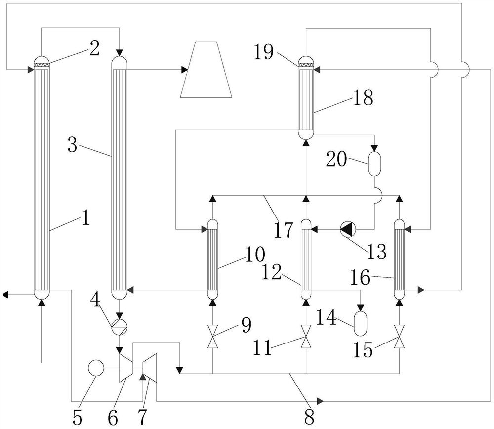
[0021] Specific implementation mode one: combine figure 1 Describe this embodiment. In this embodiment, the flue gas purification system coupled with desulfurization, denitrification and carbon capture driven by waste heat of flue gas consists of a high-temperature flue gas heat exchange tower 1, No. 1 steam-water separator 2, a low-temperature flue gas heat exchange tower 3, Flue gas water cooler 4, multiple compressors 6, multiple expanders 7, precooler inlet pipe 8, No. 1 precooler inlet valve 9, No. 1 precooler 10, No. 2 precooler inlet Gas valve 11, No. 2 pre-cooler 12, high-pressure pump 13, No. 2 liquid storage tank 14, No. 3 pre-cooler inlet valve 15, No. 3 pre-cooler 16, pre-cooler exhaust main pipe 17, flue gas Condensing tower 18, No. 2 steam-water separator 19 and No. 1 liquid storage tank 20 constitute;

[0022] The shell-side air inlet of the high-temperature flue gas heat exchange tower 1 communicates with the boiler flue gas outlet, and a No. 1 steam-water sep...

specific Embodiment approach 2

[0029] Specific Embodiment 2: This embodiment differs from Specific Embodiment 1 in that: the high-temperature flue gas heat exchange tower 1, the No. 1 precooler 10, the No. 2 precooler 12, the No. 3 precooler 16 and the flue gas The condensation tower 18 is a partitioned wall heat exchanger. Other steps and parameters are the same as those in the first embodiment.

specific Embodiment approach 3

[0030] Embodiment 3: This embodiment differs from Embodiment 1 or Embodiment 2 in that: the low-temperature flue gas heat exchange tower 3 is a regenerative heat exchanger. Other steps and parameters are the same as those in Embodiment 1 or 2.


PUM


Abstract

The invention provides a smoke gas afterheat driving desulfurization, denitration and carbon capture coupling smoke gas purification system and a smoke gas treatment method, and relates to a smoke gaspurification system and a smoke gas treatment method. In order to solve the problems that the cost of the existing desulfurization, denitration and carbon dioxide capture aiming at an industrial boiler is high, and the smoke gas utilization difficulty of the industrial boiler is great, the smoke gas afterheat energy is used for partially driving the desulfurization, denitration and carbon capturecoupling smoke gas purification process; then, the desulfurization, denitration and carbon capture are integrated; the smoke gas afterheat resources are effectively utilized; the fuel utilization efficiency is integrally improved; the comprehensive cost of the smoke gas desulfurization, denitration and carbon capture is reduced; the desulfurization rate reaches 98 percent; the denitration rate reaches 85 percent; the carbon capture rate reaches 98 percent. The system provided by the invention is applicable to desulfurization, denitration and carbon capture.

Description

technical field [0001] The invention relates to a flue gas purification system and a flue gas treatment method. Background technique [0002] For industrial boilers, waste heat loss of flue gas accounts for 10% or more of the total energy. However, because this part of the flue gas is concentrated in the range of 100-150 °C, it is a low-grade waste heat resource, which has not been effectively utilized due to the difficulty of utilization and the high cost of utilization. Sulfur dioxide and nitrogen oxides are the main gas pollutants in flue gas, and they are also the main factors causing acid rain. In order to improve the atmospheric environment, boiler air pollution emission standards are becoming more and more stringent; the existing mainstream desulfurization and denitrification technologies are limestone / gypsum wet desulfurization technology and selective catalytic reduction denitrification technology; the burden on the flue gas purification system is also becoming hea...

Claims


Application Information

Patent Timeline
Patent Type & Authority Patents(China)
IPC IPC(8): B01D53/00F28D21/00
CPCB01D53/002B01D2257/302B01D2257/404B01D2257/504B01D2258/0283F28D21/001
Inventor 吴尧刘国栋
Owner HARBIN INST OF TECH
Why Eureka
Try Eureka