Device and method for magnetically grinding inner surfaces of large-diameter long and straight pipes

A magnetic grinding and inner surface technology, applied in surface polishing machine tools, grinders, grinding/polishing equipment, etc., can solve the problems of single grinding track and large deformation of the inner groove of pipe fittings, and achieve a high degree of automation and processing. Efficient effect

Pending Publication Date: 2018-11-23
UNIV OF SCI & TECH LIAONING
2 Cites 18 Cited by

AI-Extracted Technical Summary

Problems solved by technology

[0003] Chinese patent CN107214602A discloses a device for derusting and polishing the inner wall of a magnetic tube, and CN107745326A discloses a device for polishing the inner surface of a straight pipe. Good realization of the removal of ca...

Method used

The present invention utilizes magnetic grinding method not only to be able to realize the finish processing of pipe fitting inner surface, and can effectively remove the carbon deposition, oily dirt, rust stain that piles up at pipe fitting internal groove place; Large diameter pipe fitting inner wall groove or boss can pass through The rotation of the external magnetic pole drives the rolling, jumping and tumbling of the magnetic abrasive particles inside the pipe fitting to realize the extrusion, sliding, and impact on the surface of the groove or the boss, and complete the finishing process of the inner surface of the pipe fitting. Both the magnetic pole and the workpiece can be rotated, the grinding track is complicated, and the processing efficiency is hi...

Abstract

The invention relates to a device and a method for magnetically grinding the inner surfaces of large-diameter long and straight pipes. The device comprises a bed, spindle motors, couplings, a magneticpole disc, a motor driving slide rail device and a hoisting device. Two ends of each pipe fitting can be sealed by pipe fitting plugs and are fixed by the aid of four-jaw chucks, the four-jaw chuck at one end of each pipe fitting is connected with the corresponding spindle motor by the corresponding coupling, the four-jaw chuck at the other end of each pipe fitting is connected with a support seat by bearings, support seat slide rails are fixed onto the bed, and the support seats are slidably connected with the support seat slide rails by support seat sliders; the motor driving slide rail device is arranged at the bottom of the bed, and the magnetic pole disc is connected with the motor driving slide rail device by the hoisting device, can be lifted under the control of the hoisting device and can axially move along the pipe fittings under the control of the motor driving slide rail device. The device and the method have the advantages that finish machining can be carried out on the inner surfaces of the pipe fittings by the aid of magnetic grinding processes, and carbon deposits, oil stain and rust stain which are accumulated at grooves inside the pipe fittings can be effectivelyremoved by the aid of the device and the method.

Application Domain

Technology Topic

Image

  • Device and method for magnetically grinding inner surfaces of large-diameter long and straight pipes
  • Device and method for magnetically grinding inner surfaces of large-diameter long and straight pipes
  • Device and method for magnetically grinding inner surfaces of large-diameter long and straight pipes

Examples

  • Experimental program(1)

Example Embodiment

[0033] The present invention will be described in detail below in conjunction with the accompanying drawings of the specification, but it should be pointed out that the implementation of the present invention is not limited to the following embodiments.
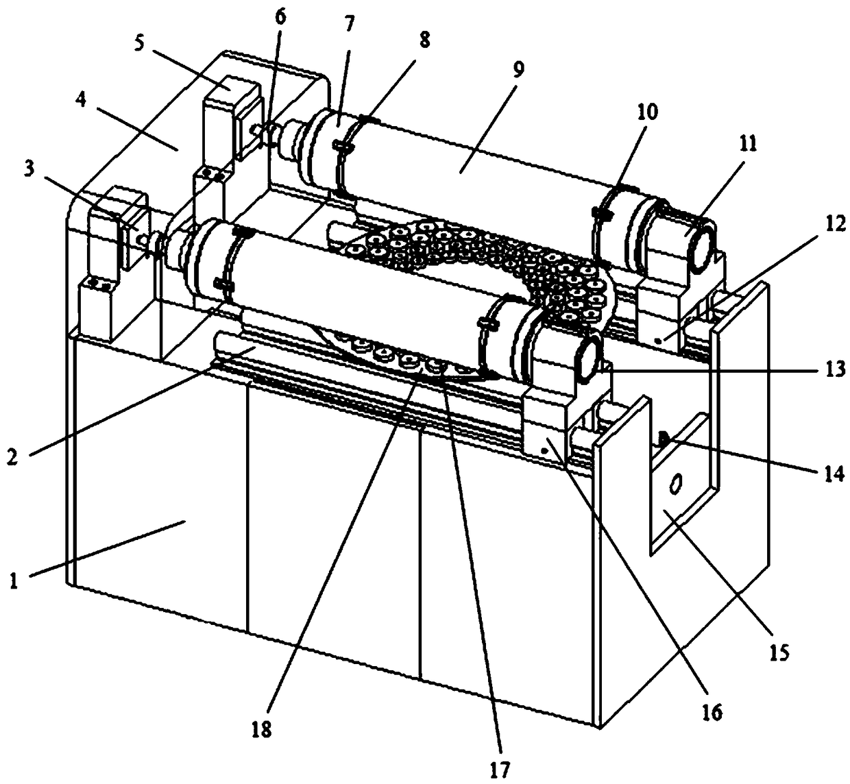
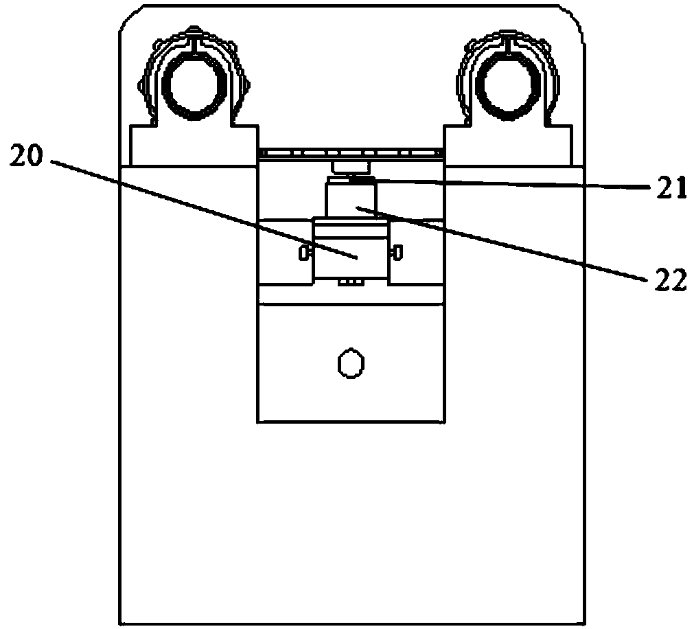
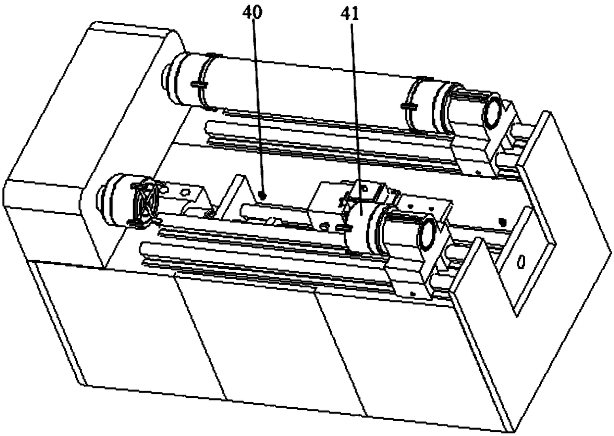
[0034] see figure 1 , figure 2 , image 3 , A magnetic grinding device for the inner surface of a large-diameter long straight tube, including a base 1, a spindle motor 3, a device housing 4, a spindle motor support base 5, a coupling 6, a four-jaw chuck 7, a magnetic pole plate 18, and a photoelectric sensor One 14. Photoelectric sensor two 40, motor-driven slide rail device 15, and lifting device 20. The device housing 4 covers the outside of the spindle motor 3 and is fixed above the base 1; the spindle motor 3 is fixed on the upper left side of the base 1 through the spindle motor support base 5; the spindle motor 3 is connected to the four-jaw chuck 7 through the coupling 6 The support seat slide rail 2 is fixed on the base 1 platform, and the support seat 11 is fixed on the support seat slide rail 2 through the support seat slider 16; the outer ring of the support seat bearing 13 and the support seat 11 are in interference fit, and the inner ring is with The support chuck 41 has an interference fit; the support slide 16 is fixed to the support slide rail 2 by locking the slide lock screw 12 on the support slide to complete the fixation of the support 11 to ensure the support chuck The distance between 41 and the four-jaw chuck 7 realizes the sealing of the pipe fitting 10 to the pipe fitting 9; see Figure 1-Figure 3 , This device can process two pipe fittings at the same time or single pipe. Two sets of transmission mechanisms are arranged on a base 1 to drive the pipes to rotate. A magnetic pole plate is arranged under the pipes. The bottom of the base 1 has two middle grooves. Side convex structure, the convex part is used to support the fixed transmission mechanism, two photoelectric sensors are installed on the side wall of the groove, the photoelectric sensor 14 and the photoelectric sensor two 40 are adsorbed on the side wall of the groove of the base 1 by magnets. The distance between the second sensor 40 and the photoelectric sensor 14 can be adjusted to realize the control of the movement distance and the movement period of the slider plate 27. The lifting device can be directly fixed at the bottom of the groove of the base 1.
[0035] see figure 1 , Figure 4 , The motor-driven slide rail device includes a slide rail motor seat 23, a slide rail motor 24, a motor screw coupling 25, a slide rail 26, a slide plate 27, a lead screw 28, a lead screw support bearing 29, a slide 30, a slide Rail base 31, slide rail baffle 32. The slide rail base 31 is installed in the groove of the machine base 1, a slide rail baffle 32 and a slide rail 26 are fixed on the slide rail base 31; a slider 30 is installed on the slide rail 26, and the slider plate 27 is fixed on the slider 30 ; The slide motor 24 is fixed in the groove of the machine base 1 through the slide motor base 23; one end of the screw 28 is connected to the slide motor 24 through the motor screw coupling 25, and the other end is fixed on the slide through the screw support bearing 29 Rail baffle 32 on. When the slider plate 27 moves to the photoelectric sensor, the photoelectric sensor sends a signal to the slide rail motor 24, and the slide rail motor 24 controls the movement distance of the slider plate 27 through forward and reverse rotation.
[0036] see figure 2 , Figure 5 , Image 6 The lifting device includes a lifting device base 33, a lifting block 34, a rotating handle 35, a handle connecting rod 36, a rack 37, and a gear 38. The lifting device base 33 is fixed on the slider plate 27 of the motor-driven slide rail device 15; the handle link 36 is fixedly connected to the gear 38, and the two are installed inside the lifting device base 33, and the two ends of the handle link 36 are connected with rotating handles 35. The gear 38 cooperates with the rack 37 on the lifting block 34 to realize the up and down movement of the lifting block 34; the lifting block 34 is fixed with a rotating magnetic pole motor base 22 on which the rotating magnetic pole motor 21 is mounted. The distance between the magnetic pole plate 18 and the pipe 9 can be adjusted to 2mm-5mm through the lifting device.
[0037] see Figure 7 , The magnetic pole disk 18 includes a large magnetic pole 17 and a small magnetic pole 39. On the magnetic pole plate 18, two rows of large magnetic poles 17 are arranged at equal intervals on the outer side, and two rows of small magnetic poles 39 are arranged on the inner side at equal intervals; the upper side of the large magnetic pole 17 and the small magnetic pole 39 are both S poles, and the lower side is N pole; The pole motor 21 is connected by a key. The magnetic pole plate 18 adopts an arrangement of small magnetic poles 39 in the inner ring and large magnetic poles 17 in the outer ring. During the finishing process, different magnetic forces are applied to the inner wall of the tube 9 to improve the finishing effect.
[0038] see Picture 8 , The chuck adopts four jaws 8, the jaws 8 are inlaid inside the chuck 7, and the four-jaw chuck 7 contacts the pipe fitting block 10 as a plane; the jaws 8 can hold the pipe fitting plug 10 and the pipe fitting 9 at the same time.
[0039] see Picture 9 , The pipe fitting is sealed in a stepped shape and is made of rubber material. The small end is embedded in the pipe fitting 9 and the outer diameter of the big end is equal to that of the pipe fitting 9.
[0040] see Figure 1-Figure 10 , A magnetic grinding method for the inner surface of a large-diameter long straight pipe, including the following steps:
[0041] 1) Magnetic abrasive particles 19 (the magnetic abrasive particles are a mixture of magnetic needles and magnetic abrasive particles, the volume ratio of the two is 1:2), mixed with water-based abrasive liquid in a ratio of 3:2, and filled into the pipe 9, the filling amount It does not exceed one third of the volume of the pipe fitting 9, and the two sides of the pipe fitting 9 are sealed by the pipe fitting block 10;
[0042] 2) Move and adjust the position of the support base 11, complete the squeezing and clamping of the pipe block 10, and lock the screw 12 on the 16 of the support base slider;
[0043] 3) Turn the rotary handle 35 on the lifting device 20 to adjust the distance between the magnetic pole plate 18 and the pipe 9;
[0044] 4) The magnetic pole disk 18 is rotated by the rotating magnetic pole motor 21. The magnetic pole disk 18 walks from the left photoelectric sensor two 40 to the right photoelectric sensor 14 under the support of the slider plate 27. The photoelectric sensor 14 sends out a signal, and the spindle motor 3 Drive the tube 9 to rotate 60 degrees, and then the magnetic pole plate 18 walks from the photoelectric sensor 14 on the right to the photoelectric sensor 2 40 on the left. The photoelectric sensor 2 40 sends out a signal. The spindle motor 3 drives the tube 9 to rotate 60 degrees in the same direction, reciprocating in sequence Movement to realize the finishing of the inner surface of the pipe 9. It is also possible to use other movement modes of rotation of the pipe 9 and rotation and translation of the magnetic pole plate 18 to realize the finishing of the inner surface of the pipe 9.
[0045] The invention uses the magnetic grinding method to not only realize the finishing processing of the inner surface of the pipe fitting, but also to effectively remove the carbon deposits, oil stains and rust stains accumulated at the inner groove of the pipe fitting; the inner wall groove or the boss of the large-diameter pipe fitting can be rotated by the external magnetic pole Drive the magnetic abrasive particles inside the pipe to roll, jump, and roll to realize the extrusion, sliding, and impact on the surface of the groove or boss, and complete the finishing of the inner surface of the pipe. Both the magnetic pole and the workpiece can be rotated, the grinding track is complicated, and the processing efficiency is high.

PUM

no PUM

Description & Claims & Application Information

We can also present the details of the Description, Claims and Application information to help users get a comprehensive understanding of the technical details of the patent, such as background art, summary of invention, brief description of drawings, description of embodiments, and other original content. On the other hand, users can also determine the specific scope of protection of the technology through the list of claims; as well as understand the changes in the life cycle of the technology with the presentation of the patent timeline. Login to view more.

Similar technology patents

Classification and recommendation of technical efficacy words

  • Improve processing efficiency
  • High degree of automation

Acid tank sealing treatment system

Owner:YANTAI JEREH PETROLEUM EQUIP & TECH

Full-automatic flexible assembly line of light emitting diode (LED) bulb lamp

InactiveCN102896494AIncreased reliability and automationHigh degree of automationAssembly machinesLight sourceStructure based
Owner:SHANGHAI RADIO EQUIP RES INST
Why Eureka
Try Eureka