Braking control method, electronic stability control system and computer readable medium

A technology of stability control and braking control, applied in the fields of braking control, computer readable media, and electronic stability control systems, can solve the problems of hindering the recovery of braking energy and less braking energy of new energy vehicles, and achieve improved Effects of recycling and waste reduction

Active Publication Date: 2020-07-03
BEIJING YINGCHUANG HUIZHI TECH
View PDF3 Cites 0 Cited by
  • Summary
  • Abstract
  • Description
  • Claims
  • Application Information

AI Technical Summary

Problems solved by technology

[0004] At present, in the traditional vacuum booster braking system, as long as the driver steps on the brake pedal, the friction brake will start to work and consume energy, which seriously hinders the braking energy recovery of new energy vehicles such as electric vehicles and hybrid vehicles, resulting in Recovers less braking energy

Method used


Image

  • Braking control method, electronic stability control system and computer readable medium
  • Braking control method, electronic stability control system and computer readable medium
  • Braking control method, electronic stability control system and computer readable medium

Examples


Embodiment 1

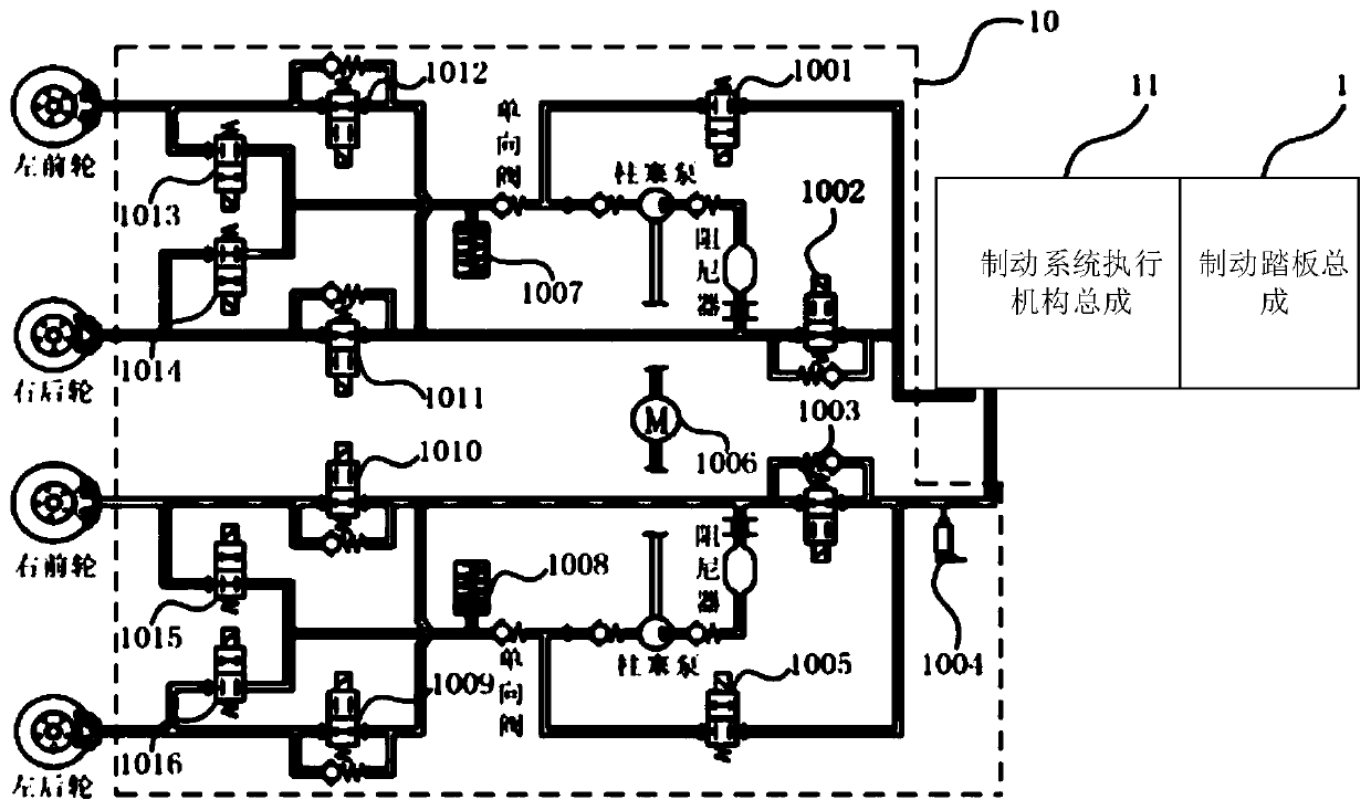
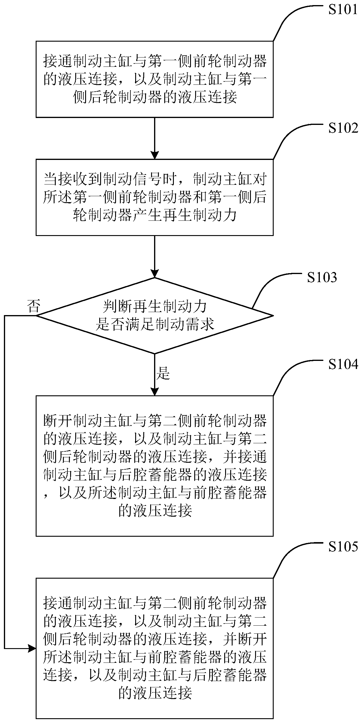
[0045] An embodiment of the present invention provides a braking control method, which is applied to the electronic stability control system ESC. The schematic diagram of the auxiliary regenerative braking control is as follows: figure 1 As shown, it includes a brake system actuator assembly 11 , a brake pedal assembly 1 and an electronic stability control system (Electrical Speed ​​Controller, ESC for short) assembly 10 . The ESC assembly 10 includes a front cavity suction valve 1001, 1002 is a front cavity pressure limiting valve, 1003 is a rear cavity pressure limiting valve, 1004 is a main cylinder pressure sensor, 1005 is a rear cavity pressure limiting valve, 1006 is a pump motor, and 1007 is a front cavity pressure limiting valve. cavity accumulator, 1008 is the rear cavity accumulator, 1009 is the left rear wheel boost valve, 1010 is the right front wheel boost valve, 1011 is the right rear wheel boost valve, 1012 is the left front wheel boost valve, 1013 Be the left f...

Embodiment 2

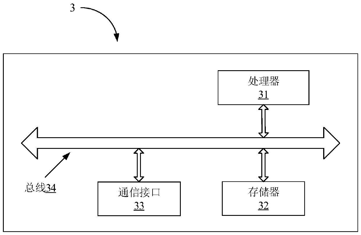
[0075] An embodiment of the present disclosure provides an electronic stability control system, such as image 3 As shown, the electronic stability control system includes: an ESC assembly (not shown in the figure), a processor 31, and a memory 32. Computer programs that can run on the processor are stored in the memory. When the processor executes the computer program, The steps of the method provided in the first embodiment above are realized.

[0076] see image 3 , the electronic stability control system further includes a communication interface 33 and a bus 34 , the processor 31 and the memory 32 are connected through the bus 34 . The processor 31 is used to execute executable modules, such as computer programs, stored in the memory 32 .

[0077] Wherein, the memory 32 may include a high-speed random access memory (RAM, Random Access Memory), and may also include a non-volatile memory (non-volatile memory), such as at least one disk memory. The communication connectio...

Embodiment 3

[0084] An embodiment of the present disclosure provides a computer-readable medium having a non-volatile program code executable by a processor, and the program code causes the processor to execute the method provided in the first embodiment above.

[0085] Those skilled in the art can clearly understand that for the convenience and brevity of description, the specific working process of the system and / or device described above can refer to the corresponding process in the foregoing method embodiment, and details are not repeated here.


PUM


Abstract

The invention provides a brake control method, an electronic stability control system and a computer readable medium. The method comprises the steps that a brake master cylinder is switched on to be in hydraulic connection with a first-side front wheel brake and to be in hydraulic connection with a first-side rear wheel brake; when a brake signal is received, the brake master cylinder can generateregenerated brake force for the first-side front wheel brake and the first-side rear wheel brake. According to the brake control method, the electronic stability control system and the computer readable medium, the problem in the prior art that the recovery amount of brake energy is low is solved; when a driver steps on a brake pedal, the intervention of friction brake is stopped, a regenerated brake motor converts partial kinetic energy generated when a vehicle is braked into energy of other forms, and then the energy is stored in an energy storage unit through a converting device; meanwhile, the speed reduction control over the vehicle is achieved through the generation of certain brake force, thus recycling of the brake energy is promoted, and the waste of the brake energy is reduced.

Description

technical field [0001] The invention relates to the technical field of automobiles, in particular to a braking control method, an electronic stability control system and a computer readable medium. Background technique [0002] The braking system is a special device that exerts a certain external force on a certain part of the car, so as to realize the forced braking of the wheels of the car to a certain extent. The cars running on the ramp keep running at a steady speed, so that the stopped cars can be parked stably. [0003] The service brake system is operated by the driver with his feet, so it is also called the foot brake system. Its function is to slow down the moving car or stop it in the shortest distance. The parking brake system is controlled by the driver's hand, so it is also called the hand brake system. Its function is to make the car parked on various road surfaces stay in place. The second brake system refers to a set of devices to ensure that the car can s...

Claims


Application Information

Patent Timeline
Patent Type & Authority Patents(China)
IPC IPC(8): B60T13/14B60L7/24
CPCB60L7/24B60T13/14B60T2270/604
Inventor 雍加望林甲胜张璞俞伟康雅文
Owner BEIJING YINGCHUANG HUIZHI TECH
Why Eureka
Try Eureka