Firearm laser calibrator, method for demarcating firearm laser calibrator, method for calibrating firearm and method for determining target point of bore axis

A technology of calibrator and laser, which is applied in the field of calibrating guns and determining the target point of the bore axis, calibration, and laser calibrator for firearms. It can solve the problems of inability to determine the extension line of the bore axis, low calibration accuracy, and unchanged operation. Achieve the effects of improving the combat effectiveness of the troops, the calibration process is fast and accurate, and the operation and use are convenient

Pending Publication Date: 2018-11-23
ARMY ENG UNIV OF PLA
View PDF2 Cites 8 Cited by
  • Summary
  • Abstract
  • Description
  • Claims
  • Application Information

AI Technical Summary

Problems solved by technology

[0005] One of the purposes of the present invention is to provide a firearm laser calibrator to solve the problems of existing firearm calibrator with complex structure, unchanged operation, low calibration accuracy and large error
[0006] The second purpose of the present invention is to provide a marking method for determining the extension line of the bore axis, so as to solve the problem that the determination of the position of the extension line of the bore axis on the target cannot be realized at present

Method used


Image

  • Firearm laser calibrator, method for demarcating firearm laser calibrator, method for calibrating firearm and method for determining target point of bore axis
  • Firearm laser calibrator, method for demarcating firearm laser calibrator, method for calibrating firearm and method for determining target point of bore axis
  • Firearm laser calibrator, method for demarcating firearm laser calibrator, method for calibrating firearm and method for determining target point of bore axis

Examples


Embodiment 1

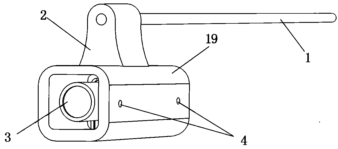
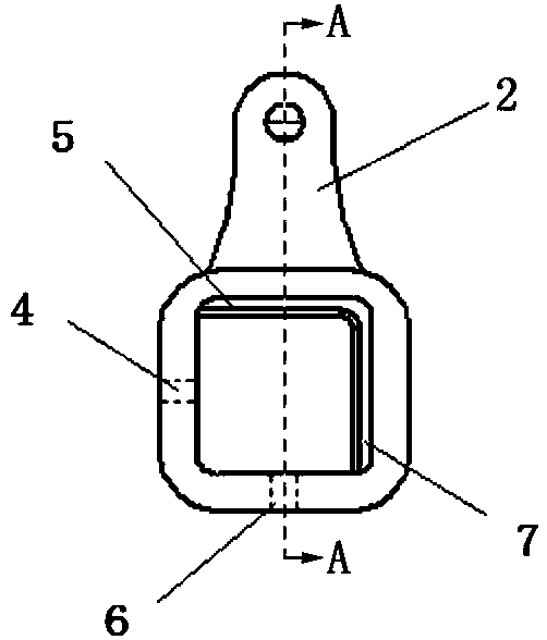
[0064] The structure of the gun laser aligner in this embodiment is as follows figure 1 As shown, it includes a plunger 1, a laser fixing frame and a laser generator 3.

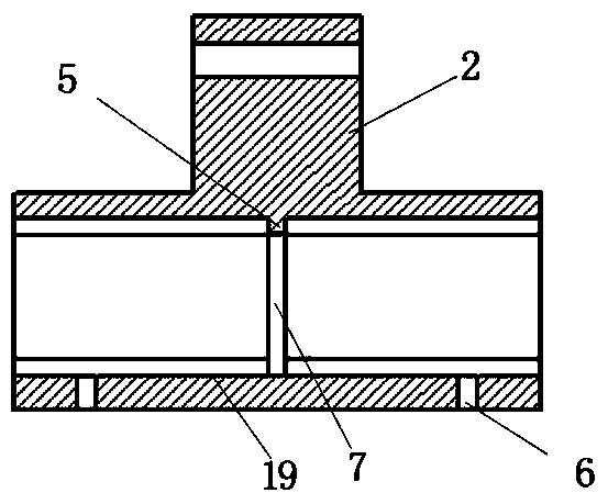
[0065] The plunger 1 is rod-shaped as a whole, preferably a straight-handled round rod body, and its diameter is slightly smaller than the inner diameter of the male side of the inner spiral of the barrel of the firearm to be calibrated, so that the plunger can be smoothly inserted into the barrel from the muzzle and can Free rotation. The laser fixing frame is composed of a positioning cylinder 19 and a plunger positioning member 2 arranged on the upper side of the positioning cylinder 19. The front end of the plunger 1 is fixedly connected to the plunger positioning member 2. The positioning cylinder 19 is used to fix the laser generator 3, and the laser generator 3 is arranged in the positioning cylinder 19 of the laser fixing frame for emitting positioning laser light to the front target. The cross-section ...

Embodiment 2

[0069] Combine Figure 7 This embodiment provides a specific method for determining the target point of the 95-type rifle barrel axis extension line on the target, including the following steps:

[0070] ① Set up a stand with a longitudinal jack 22, the inner diameter of the longitudinal jack 22 is the same as the inner diameter of the male side of the inner spiral line of the barrel of the firearm to be tested, and the length between the front and rear ports of the longitudinal jack 22 is greater than that of the firearm Half the length of the plunger 1 in the laser collimator;

[0071] ②Set the target 20 in front of 100 meters from the front end of the bracket, and make a marking point 21 on the target 20, and adjust the bracket so that the axis of the longitudinal jack 22 on the bracket points to the marking point;

[0072] ③ Insert the plunger 1 of the laser aligner of the firearm into the longitudinal jack 22 of the bracket;

[0073] ④Turn on the laser generator 3, adjust the las...

Embodiment 3

[0078] Combine Figure 7 This embodiment provides a method for calibrating a laser calibrator for firearms, which includes the following steps:

[0079] ① Set up a bracket with a longitudinal jack 22. The inner diameter of the longitudinal jack 22 is the same as the inner diameter of the male side of the inner thread of the barrel of the firearm to be calibrated, and the length between the front and rear ports of the longitudinal jack 22 is greater than that of the firearm Half the length of the plunger 1 in the laser collimator;

[0080] ②Set the target 20 in front of 100 meters from the front end of the bracket, and make a mark 21 on the target 20, adjust the bracket so that the axis of the longitudinal jack 22 on the bracket is aligned with the mark 21;

[0081] ③ Insert the plunger 1 of the laser aligner of the firearm into the longitudinal jack 22 of the bracket;

[0082] ④Turn on the laser generator 3 and adjust the laser generator 3 on the laser aligner of the gun to make the l...


PUM


Abstract

The invention discloses a firearm laser calibrator, a method for demarcating the firearm laser calibrator, a method for calibrating a firearm, and a method for determining the target point of the boreaxis. The firearm laser calibrator comprises an inserted rod, a laser fixing frame and a laser generator, wherein the inserted rod is in a straight-handle rod shape, the diameter of the inserted rodis slightly less than the sunny side inner diameter of a gun barrel inner rotation line of a calibrated firearm, so that the inserted rod is smoothly inserted and connected into a gun barrel from a gun muzzle; the laser fixing frame includes a positioning cylinder for fixing the laser generator and an inserted rod positioning piece arranged on the upper side of the positioning cylinder, and the front end of the inserted rod is fixedly connected to the inserted rod positioning piece; and the laser generator is arranged in the positioning cylinder of the laser fixing frame. By means of the firearm laser calibrator, the purpose of calibrating the firearm can be achieved, and the accurate positioning of the extension line on the bore axis can also be achieved, the firearm laser calibrator is simple in structure, and convenient to use, the calibration work of the general light weapons such as rifles without live firing can be achieved, the calibration process is fast and accurate, and the firearm laser calibrator is very suitable for the use of the gun application unit of a basic level which lacks the special gun calibrator equipment.

Description

Technical field [0001] The patent of the invention relates to a firearm calibration device, specifically a firearm laser calibrator, a method for calibrating and calibrating the gun and determining the target point of the barrel axis. Background technique [0002] Whether it is a firearm manufacturing factory, the army, or the public security, the firearms need to be calibrated before they are used. The existing firearm calibration device has a huge structure and is very complicated, and most of them are installed indoors for precise calibration of firearms produced and maintained. For units with guns such as grassroots companies, they do not have the conditions to use such large-scale calibration equipment. Its gun calibration work is basically carried out after a large number of bullets are tested at the shooting range, and then calibrated by analyzing the impact point. This gun calibration method not only causes a large amount of bullet consumption and wear of the firearms, ...

Claims


Application Information

Patent Timeline
Patent Type & Authority Applications(China)
IPC IPC(8): F41G1/16
CPCF41G1/16
Inventor 陈英杰张焕王广龙王瑞林
Owner ARMY ENG UNIV OF PLA
Why Eureka
Try Eureka