Central shaft torque detection system

A detection system and shaft torque technology, applied in force/torque/work measuring instruments, mechanical bearing testing, fluid pressure measurement involving magnet displacement, etc., can solve the problem of poor durability and the inability to respond accurately and timely to the shaft torque , short sensor life and other issues, to achieve the effect of improving riding comfort, improving man-machine synchronization, and accurate torque

Active Publication Date: 2018-11-23
ANNAIDA DRIVE TECH JIANGSU CO LTD
View PDF14 Cites 4 Cited by
  • Summary
  • Abstract
  • Description
  • Claims
  • Application Information

AI Technical Summary

Problems solved by technology

[0005] (1) Using a speed-type false power-assisted sensor, only the actual speed of the power-assisted bicycle is detected and the torque of the center shaft is not detected, resulting in a large difference between the power-assisted bicycle provided by the power-assisted bicycle and the power actually needed, with low precision and poor effect
[0006] (2) Install a set of elastic elements between the central shaft and the crankshaft or between the motor and the flywheel, and use the slip displacement of the elastic element after being deformed by force to drive the corresponding mechanical action, and generate physical quantities such as magnetic field and light quantity between the static sensor device The change is converted into electricity to detect the pedaling force of the cyclist; after the elastic element is deformed and pushed to do mechanical action, it will inevitably encounter resistance, which will limit the range of deformation and mechanical action, and will not be strong at all. The detection signal is further reduced, resulting in low detection sensitivity, poor consistency and stability; in addition, the elastic element will produce irreversible deformation after a long period of use, resulting in a further reduction in detection accuracy
[0007] (3) Install a set of elastic elements between the central shaft and the crankshaft or between the motor and the flywheel, and install pulse generators at both ends of the elastic elements, and use the slip displacement of the elastic elements after being deformed by force to make the two The phase difference between the pulse trains is converted by the phase detection circuit to detect the pedaling force of the bicycle; because different pedaling frequencies will produce different pulse frequencies, resulting in the same force corresponding to different phase differences, the algorithm is complex and the consistency is poor
[0008] (4) A deformable body is set between the rotating central shaft and the sprocket bracket, the strain gauge is directly pasted, and an amplifying circuit is set, which is connected with the outside world with slip rings and electric brushes; the sensor in this detection system is always rotating, and the slip ring And the brush will produce irrecoverable loss during the rotation process, resulting in short sensor life and poor durability
[0009] (5) A deformable body is set between the rotating central shaft and the sprocket bracket, and special materials are pasted on it to cause a change in magnetic permeability after being stressed, causing a change in the inductance of the coil group that is matched with it and does not rotate with it. Detect the inductance or coupling coefficient and convert it into the corresponding electric quantity; the disadvantage of this detection system is that the process is complicated and the cost is high
[0010] (6) Install a movable pressure wheel on the main circuit of the chain, detect the displacement of the pressure wheel under the tension of the chain, and produce changes in physical quantities such as magnetic field and light quantity between the static sensor and the static sensor, and convert it into electricity. The pedaling force of the rider; this kind of detection system has poor versatility and consistency, and it needs the special cooperation of the frame to achieve the effect, and some models cannot be used
However, when the crank rotates to some angles of rotation, because the effective force arm is very small, the pedaling force that makes people pedal the pedals can not be used to form the dynamic moment. If at these angles of rotation, the cyclist suddenly When the pedaling force is greatly increased, the change of the dynamic torque will be very small, so that the torque of the center shaft cannot respond accurately and timely, giving the rider a very bad riding experience
However, the existing center shaft torque detection system does not take any effective measures for this problem

Method used


Image

  • Central shaft torque detection system
  • Central shaft torque detection system
  • Central shaft torque detection system

Examples


Embodiment 1

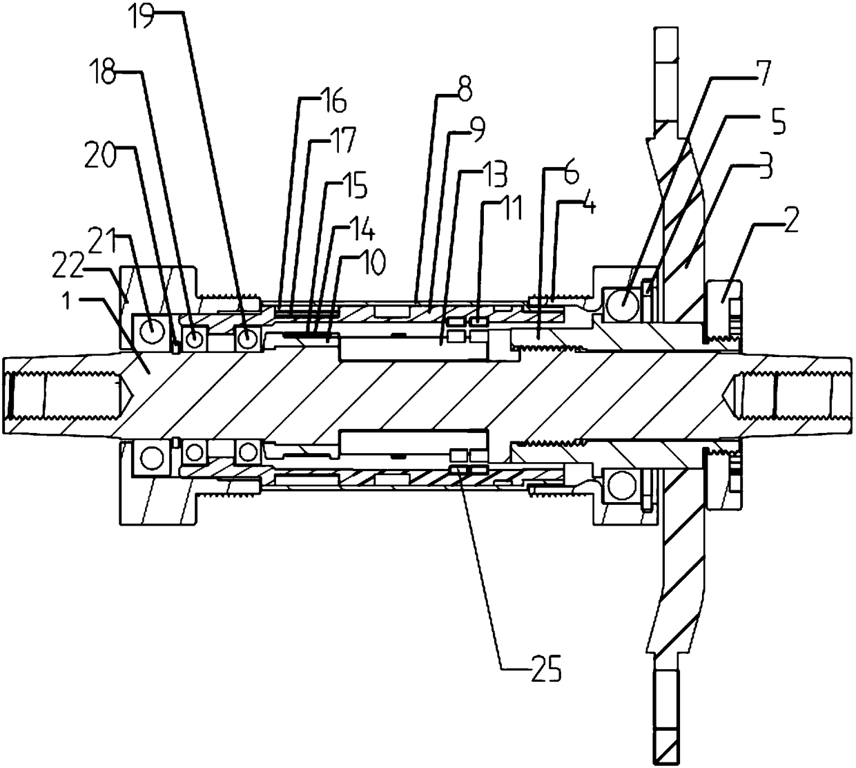
[0057] Embodiment 1 is basically as attached figure 1 As shown: the central shaft 1 torque detection system includes a lock nut 2, a claw 3, a left headset 22, a right headset 4, a central shaft 1, a deformation bridge 6, a sleeve and a magnetic isolation sleeve 10.

[0058] Such as figure 1 As shown in and , the left end and the right end of the central axis 1 are respectively connected to the left crank of the left pedal and the right crank of the right pedal by fastening screws, the left crank is located on the left side of the left headset 22, and the right crank is located on the right headset 4 to the right. An external thread is formed on the outer surface of the central axis 1 at the position connected to the deformation bridge 6 . The deformable bridge 6 is sleeved on the central shaft 1, and the deformable bridge 6 and the central shaft 1 are connected by reverse threads, and the threaded part of the central shaft 1 is locked with the internal thread of the deforma...

Embodiment 2

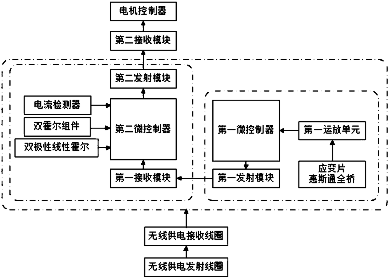
[0112] Such as Figure 6 As shown, the difference between this embodiment and Embodiment 1 is that the double Hall assembly and the bipolar linear Hall 26 are connected in the torque acquisition circuit, and the first micro-controller obtains the characteristic pedaling frequency and the centering frequency from the double Hall assembly. For the electrical signal of the rotation direction of the shaft 1, the first microcontroller obtains the electrical signal representing the crank rotation angle from the bipolar linear Hall 26, and transmits these electrical signals to the torque processing control circuit. At this time, the two circuits can be arranged together on the central axis 1 or separately, the torque acquisition circuit is arranged on the central axis 1 and the torque processing control circuit is arranged on the mounting sleeve 9 . When the torque acquisition circuit and the torque processing control circuit are set separately, the first transmitting module and the ...

Embodiment 3

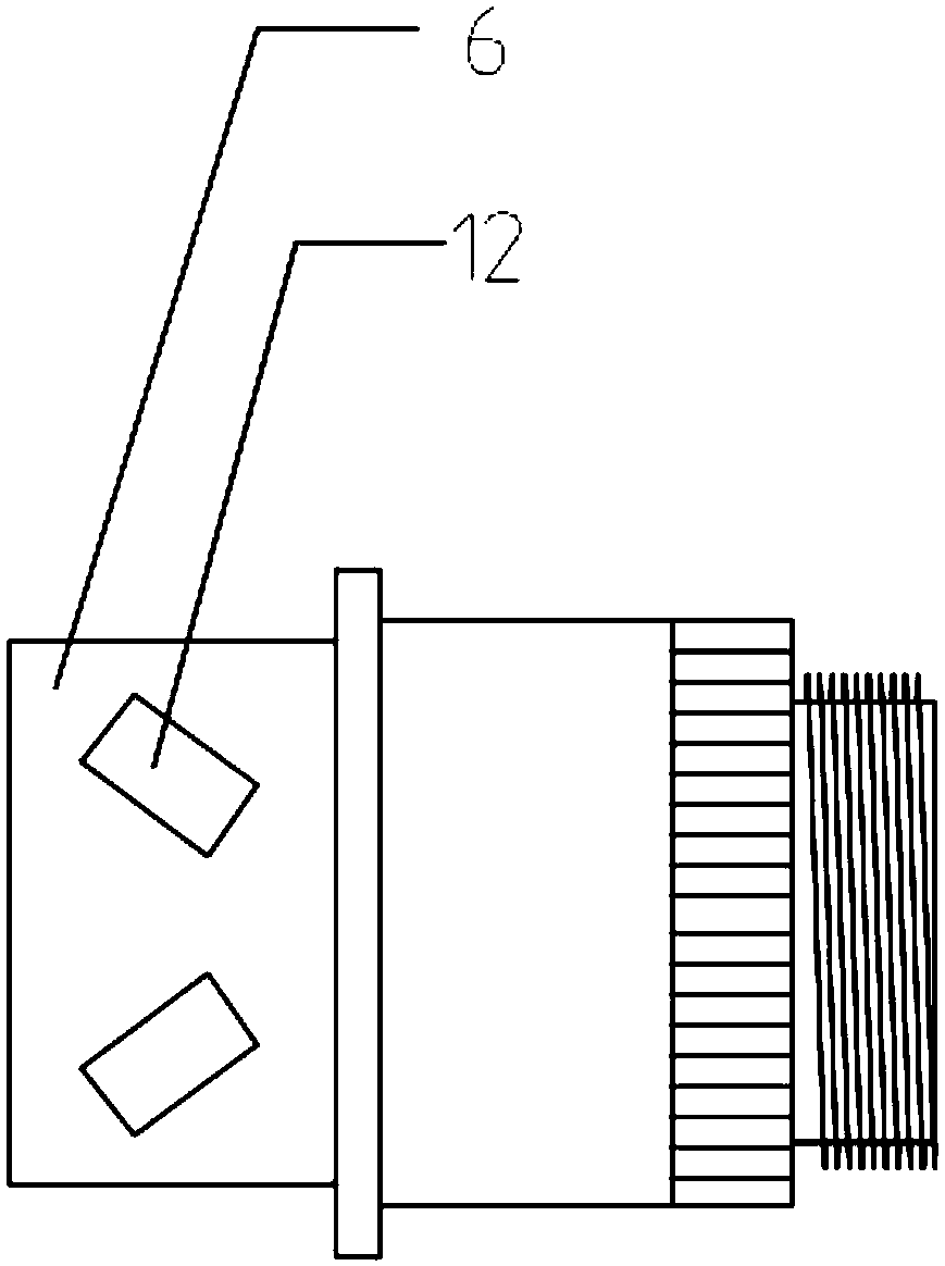
[0114] Such as Figure 7 As shown, the difference between this embodiment and Embodiment 1 is that the double Hall assembly and the strain gauge 12 units are connected in the torque acquisition circuit, and the first micro-controller obtains the characteristic pedaling frequency and the rotation of the central shaft 1 from the double Hall assembly. As for the electrical signal of the direction, the bipolar linear Hall 26 is connected in the torque processing control circuit, and the second micro-controller obtains an electrical signal representing the rotation angle of the crank from the bipolar linear Hall 26. At this time, the two circuits can be arranged together on the central axis 1 or separately, the torque acquisition circuit is arranged on the central axis 1 and the torque processing control circuit is arranged on the mounting sleeve 9 . When the torque acquisition circuit and the torque processing control circuit are set separately, the first transmitting module and t...


PUM


Abstract

The invention relates to the power-assisted bicycle driving technical field, and specifically discloses a central shaft torque detection system comprising a sleeve, a deformation bridge and a circuitboard; the deformation bridge is provided with a strain gage unit; one end of the deformation bridge is fixedly connected with the central shaft, and the other end is suspended; the sleeve comprises amount sleeve that moves with respect to the central shaft; a multi-pole magnetic ring and two single-polarity switch Halls that rotate with the central shaft so as to synchronically form relative motions are arranged between the mount sleeve and the central shaft; the multi-pole magnetic ring comprises a plurality of N poles and S poles connected one another; the dual-Hall assembly comprises twosingle-polarity switch Halls that respectively make relative motions along the periphery of the multi-pole magnetic ring; one of the two single-polarity switch Halls of the dual-Hall assembly senses Npoles, and the other senses S poles. The central shaft torque detection system can accurately detect the torque.

Description

technical field [0001] The invention relates to the technical field of power-assisted bicycle driving, in particular to a central axis torque detection system of a power-assisted bicycle. Background technique [0002] Power-assisted bicycles, also known as power-assisted electric bicycles, are a riding tool between bicycles and electric vehicles. They provide the kinetic energy needed for bicycles through electric power to assist manpower. The product of an environmentally friendly lifestyle. [0003] The central axis refers to the structure used to connect two pedals on the power-assisted bicycle and drive the claws and the chain on the claws to rotate. The central axis is the core component of the power-assisted bicycle, which is used to drive and control the normal driving of the whole vehicle. When the cyclist is riding, he needs to drive the central shaft to rotate by pedaling, and then drive the claws connected to the central shaft to rotate, the claws drive the chain...

Claims


Application Information

Patent Timeline
Patent Type & Authority Applications(China)
IPC IPC(8): G01L5/00G01L9/14G01M13/04
CPCG01L5/0023G01L5/0076G01L9/14G01M13/04
Inventor 夏静满胡江勇李家成
Owner ANNAIDA DRIVE TECH JIANGSU CO LTD
Why Eureka
Try Eureka