
Built-in online dynamic balance device test bed for main shaft

A built-in, test bench technology, applied in the direction of static/dynamic balance test, measuring device, machine/structural component test, etc. Various requirements and other issues, to achieve the effect of reasonable layout, convenient construction, and guaranteed reliability

Active Publication Date: 2018-11-23
XI AN JIAOTONG UNIV
View PDF7 Cites 4 Cited by
  • Summary
  • Abstract
  • Description
  • Claims
  • Application Information

AI Technical Summary

Problems solved by technology

[0003] The existing online dynamic balancing devices have various limitations under high-speed conditions, because the reliability of the device cannot be guaranteed under high-speed conditions. The most commonly used grinding machine spindles in industrial sites are built-in online dynamic balancing devices. It is necessary to continue research on the high-speed spindle built-in online dynamic balancing device
[0004] The research work of the built-in online dynamic balancing device is inseparable from the test verification. The test bench must not only be able to simulate the unbalanced vibration of the main shaft of the grinding machine, but also need to be installed in a suitable position for the online dynamic balancing device. The existing workbench cannot meet this requirement. Therefore, it is urgent to develop a test bench with a suitable structure, which can be applied to the research work of online dynamic balancing device.

Method used


Image

  • Built-in online dynamic balance device test bed for main shaft
  • Built-in online dynamic balance device test bed for main shaft
  • Built-in online dynamic balance device test bed for main shaft

Examples


Embodiment Construction

[0023] The present invention will be described in detail below in conjunction with the accompanying drawings and embodiments.

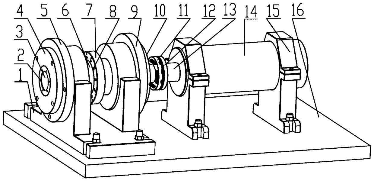
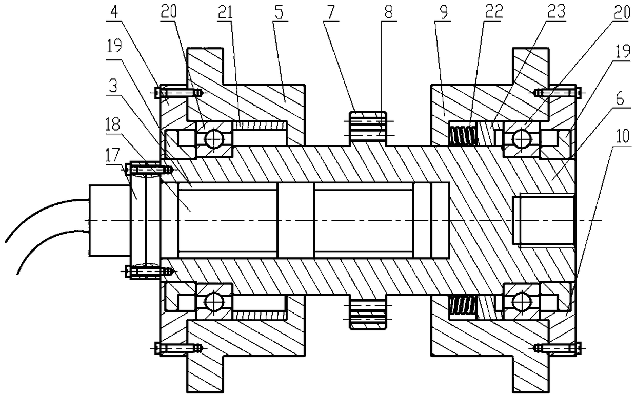
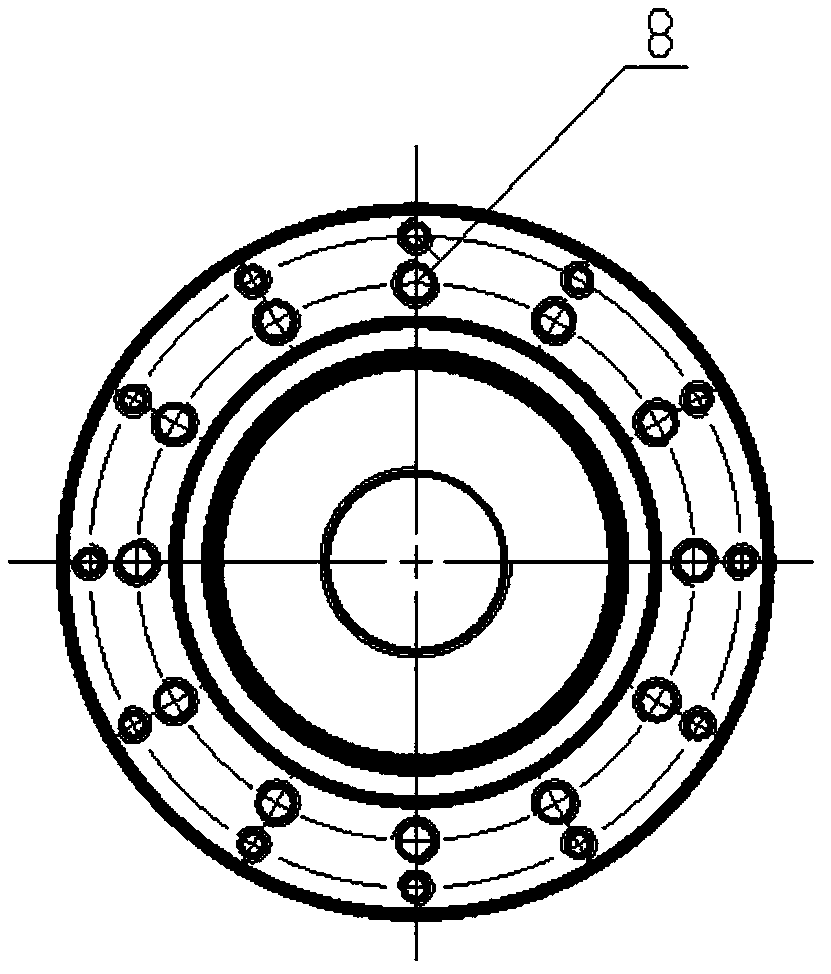
[0024] Such as figure 1 As shown, a spindle built-in online dynamic balancing device test bench includes a vibration isolation and shock absorption workbench 16. Two electric spindle bases 15 arranged front and back are connected to the vibration isolation and shock absorption workbench 16, and the electric spindle base 15 is installed There is an electric spindle 14, the front end of the electric spindle 14 is connected with a tool handle connector 13, the tool handle connector 13 is connected with the rear flange connector 12, and the rear flange connector 12 is connected with the front flange mounted on the rear end of the driven shaft 6 Part 11 realizes the transmission of motion through flexible connection, so as to achieve the purpose of driving the driven shaft 6 to rotate during the operation of the electric spindle 14; the driven shaft 6 is f...


PUM


Abstract

A built-in online dynamic balance device test bed for a main shaft comprises an electric spindle fixed on a vibration isolation damping workbench through an electric spindle base. The front end of theelectric spindle is connected with a rear flange connecting piece through a knife handle connecting piece, and the rear flange connecting piece is flexibly connected with a front flange connecting piece arranged at the rear end of a driven shaft. The driven shaft is fixed to a base through a front bearing support and a rear bearing support, and the base is fixed on the vibration isolation dampingworkbench. The front section of the driven shaft is provided with a built-in hole for installing an online dynamic balance device, and a threaded hole used for mounting the front flange connecting piece is formed in the rear section of the driven shaft. Counterweight threaded holes are uniformly distributed in an unbalanced simulation plate arranged on the outer side of the middle of the driven shaft, and the mass distribution of the unbalanced simulation plate is changed through installation of screws. The simulation of unbalanced vibration is carried out. The test research requirements of abuilt-in online dynamic balance device can be completely met, and the built-in online dynamic balance device test bed is convenient to construct.

Description

technical field [0001] The invention relates to the technical field of a spindle online dynamic balancing device test bench, in particular to a spindle built-in online dynamic balancing device test bench. technical background [0002] Rotor vibration caused by unbalance is one of the most common faults in rotating machinery. In high-speed and high-precision machine tools, the vibration of the main shaft affects the life of the machine tool and the machining accuracy of the parts. How to reduce vibration has become a problem that needs to be solved in industrial production. In order to ensure production efficiency, high-speed and efficient dynamic balancing technology is required, so online dynamic balancing technology came into being. The more mature and practical online dynamic balancing technology is to install a dynamic balancing device on the main shaft, and use this device to complete the dynamic balancing work; now there are three main types of online dynamic balancin...

Claims


Application Information

Patent Timeline
Patent Type & Authority Applications(China)
IPC IPC(8): G01M1/38
CPCG01M1/32
Inventor 梅雪松运侠伦袁世珏姜歌东胡振邦
Owner XI AN JIAOTONG UNIV
Learn More