
Moisture content measuring device based on plug-in conductivity sensor

A technology of conductance sensor and measuring device, which is applied to measuring devices, instruments, scientific instruments, etc., can solve the problems of high cost, uneven distribution of electrode distances, electrode facing area, and difficulty in determining electrode spacing.

Inactive Publication Date: 2018-11-23
TIANJIN UNIV
View PDF10 Cites 2 Cited by
  • Summary
  • Abstract
  • Description
  • Claims
  • Application Information

AI Technical Summary

Problems solved by technology

Although the excitation field distribution of this kind of electrode is uniform, there are problems such as the edge effect of the force line, the electrode facing area, and the electrode spacing are difficult to determine. It is suitable for square pipes; although the opposite wall arc electrode solves the problem of parallel plate electrodes, it also causes The distance distribution between the electrodes is uneven, that is, the distance between the middle of the electrodes is far and the distance between the electrodes is close, resulting in uneven distribution of the excitation field, which affects the measurement information; the mesh electrode structure can better reflect the full pipeline cross-section at the same time In addition, cross-sectional multi-electrode (such as ERT imaging technology) can also accurately measure the distribution of two-phase flow in the pipeline, but both have the problems of complex structure, inconvenient installation and high cost

Method used


Image

  • Moisture content measuring device based on plug-in conductivity sensor
  • Moisture content measuring device based on plug-in conductivity sensor
  • Moisture content measuring device based on plug-in conductivity sensor

Examples


Embodiment Construction

[0017] The present invention will be described in detail below in conjunction with the accompanying drawings and embodiments.

[0018] The present invention mainly comprises the design of sensor design, signal processing unit, effective value measuring unit and calculating unit, and concrete design is as follows:

[0019] 1. Sensor design

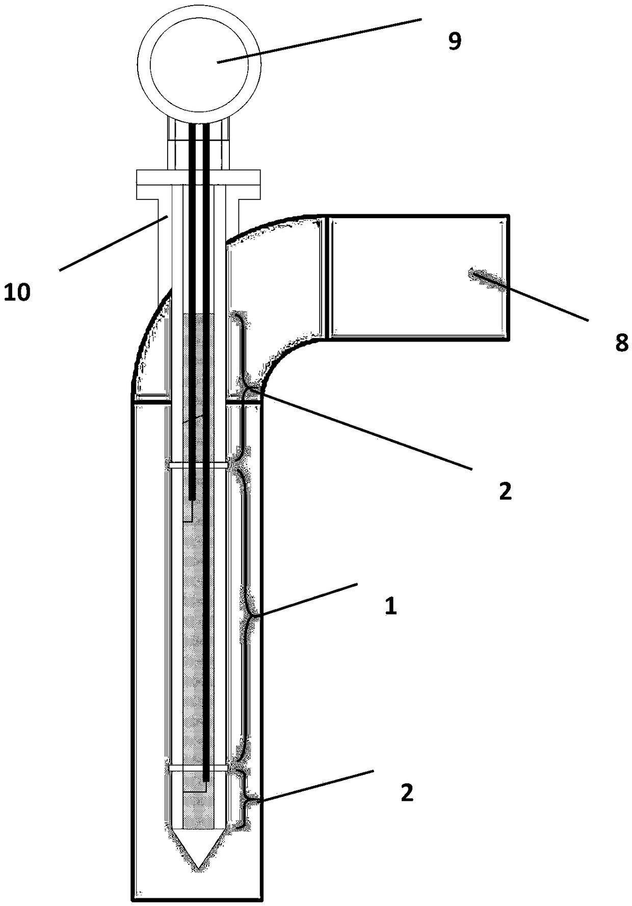
[0020] Such as figure 1 As shown, the plug-in conductivity sensor consists of an excitation measurement electrode in the middle and two guard electrodes above and below. Among them, the excitation and measurement share the same electrode of the sensor, and the metal pipe connected to the ground is used as the reference ground. When installing, the sensor is inserted from top to bottom along the direction of the vertical pipeline, so that the electrode is located at the axis of the vertical pipeline. The excitation measurement electrode and the protection electrode of the sensor are lead to the signal processing unit respectively, and the...


PUM


Abstract

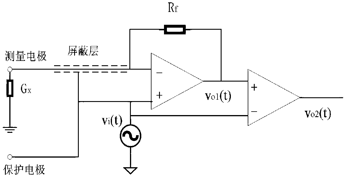
The invention relates to a moisture content measuring device based on a plug-in conductivity sensor. The moisture content measuring device comprises a conductivity sensor, a signal processing unit, avirtual value measuring unit and a computing unit; the conductivity sensor comprises an exciting measuring electrode which is used as an exciting electrode and a measuring electrode at the same time and two protecting electrodes which are fixed above and under the exciting measuring electrode; the signal processing unit comprises a front-end amplifier, a coaxial cable, an alternating current signal generator and a differential amplifier; a negative input end of the front-end amplifier is connected with the exciting measuring electrode in the conductivity sensor by a coaxial cable signal wire;a positive input end of the front-end amplifier is connected with the alternating current signal generator and meanwhile is connected with the two protecting electrodes in the conductivity sensor, a shielding layer of the coaxial cable and a negative input end of the differential amplifier; a standard resistor is connected with the negative input end and the output end of the front-end amplifier;the output end of the front-end amplifier is connected with the positive input end of the differential amplifier.

Description

technical field [0001] The invention relates to the field of oilfield exploitation, in particular to a water content measuring device based on an insertable conductivity sensor. Background technique [0002] The development of today's society has an increasing demand for energy, and oil, as the "primary energy source", plays a very important role in the national economy and national strategy. However, petroleum is a non-renewable energy source, so it is of great significance to minimize mining losses and make full use of resources during the mining process. In petroleum engineering, in order to improve the extraction efficiency of crude oil, high-pressure water injection and polymer injection technologies are often used in the secondary recovery of oil wells. However, this process makes the extracted crude oil contain water, leading to the ubiquitous oil-water two-phase flow in the process of oil well exploitation and post-exploitation transmission, and the water content is...

Claims


Application Information

Patent Timeline
IPC IPC(8): G01N27/04
CPCG01N27/048
Inventor 王超张帅孙宏军曹晴晴李潇亮王伟
Owner TIANJIN UNIV
Learn More