Near-field circumferential SAR rapid three-dimensional imaging method

A technology of three-dimensional imaging and two-dimensional imaging, which is applied in the field of three-dimensional imaging to achieve precise imaging, improve computing speed, and solve the effects of rotation angle restrictions

Active Publication Date: 2018-11-23
NORTHWESTERN POLYTECHNICAL UNIV
View PDF5 Cites 9 Cited by
  • Summary
  • Abstract
  • Description
  • Claims
  • Application Information

AI Technical Summary

Problems solved by technology

[0004] In order to overcome the limitation of the existing algorithm on the rotation angle and the lack of three-dimen

Method used


Image

  • Near-field circumferential SAR rapid three-dimensional imaging method
  • Near-field circumferential SAR rapid three-dimensional imaging method
  • Near-field circumferential SAR rapid three-dimensional imaging method

Examples


Example Embodiment

[0057] The example is as follows:

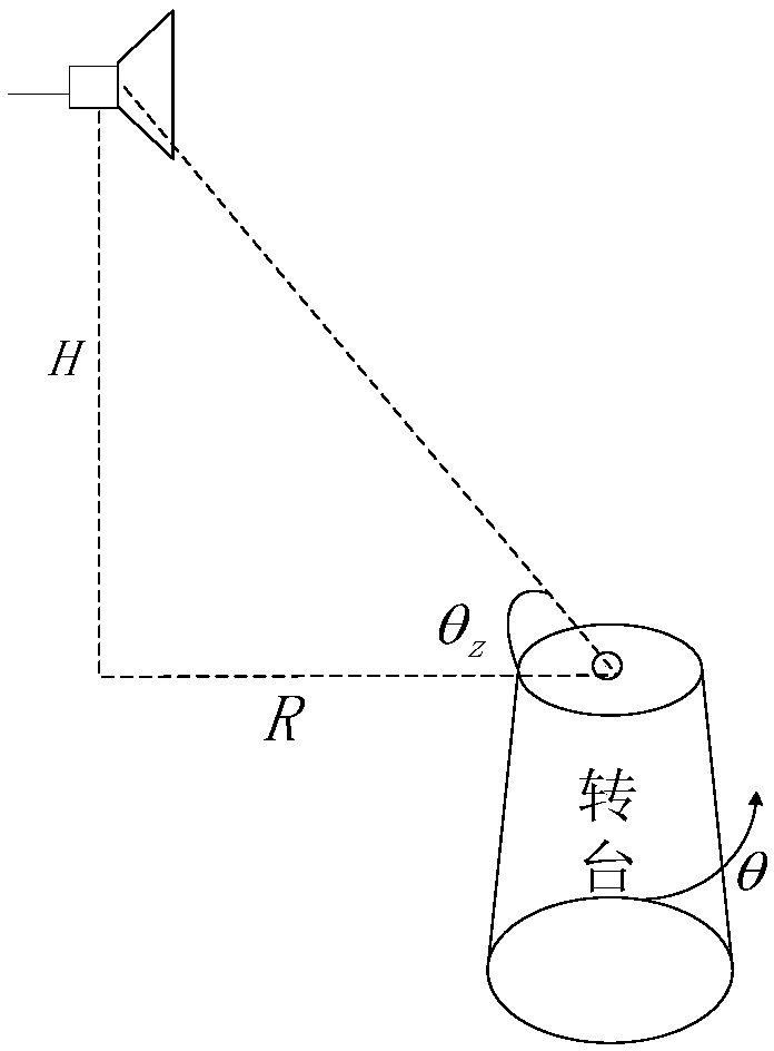
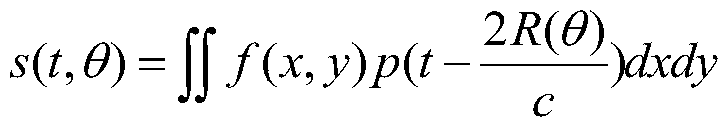
[0058] Step 1: Obtain the echo data of two-dimensional imaging: Firstly, ignore the influence of height on imaging and reduce the target dimension from three-dimensional to two-dimensional. It is assumed that all points on the height in the scene are located on the ground plane. The radar transmits a chirp signal p(t) to the target, and the target reflection function is set to f(x,y). According to the circular SAR geometric imaging model, the target echo signal s(t,θ), s(t,θ) can be expressed for:

[0059]

[0060] Where c represents the speed of light, R(θ) represents the distance between the radar and the target under the angle θ when the target rotates with the radar, R represents the horizontal distance between the radar and the center of the turntable, which is equivalent to the radius of movement of the radar, and H represents the vertical height between the radar and the ground.

[0061] In this embodiment, the center frequency is S-band, ...


PUM


Abstract

The invention provides a near-field circumferential SAR rapid three-dimensional imaging method, and relates to the field of microwave imaging. Firstly, the target is converted into the polar coordinate format to obtain the target echo, and then analysis is performed by using the wave spectrum theory and the two-dimensional imaging result of the target is obtained by using the mode of angle domainconvolution calculation and frequency domain integration operation. The target scattering characteristic functions of different altitude surfaces are accordingly obtained through different altitude values and the information of different altitude surfaces is superposed so as to obtain the three-dimensional imaging result. The idea of combining Green's function decomposition and tomography is utilized to improve the operation speed of near-field circumferential imaging and also improve the image resolution, the target echo is precisely focused by using the Green's function decomposition technology so that the limitation of the rotation angle by the focusing convolution integration method is effectively solved, and the three-dimensional imaging result is obtained by using the idea of tomography. The target echo data can be precisely imaged effectively through the simulation result.

Description

technical field [0001] The invention relates to the field of microwave imaging, in particular to a three-dimensional imaging method. Background technique [0002] Circular SAR (Circular SAR, CSAR) is a special curved synthetic aperture radar mode. The radar platform rotates and moves around the center of the scene to form a circular trajectory, and the echo data of the scene is recorded in all directions to meet the needs of higher refined observation. Compared with the conventional synthetic aperture radar imaging mode, the circular SAR system has the following unique advantages: (1) It can obtain the scattering characteristics of the target in all directions, the ability to extract target scattering information is stronger, and the imaging accuracy is higher; (2) It is effective to broaden the wavenumber domain bandwidth, and the theoretical resolution reaches sub-wavelength order, which makes low-band high-resolution imaging possible, and is more conducive to the observat...

Claims


Application Information

Patent Timeline
IPC IPC(8): G01S13/90
CPCG01S13/904G01S13/9094G01S13/9088
Inventor 王保平马健钧韩昭旋张研方阳
Owner NORTHWESTERN POLYTECHNICAL UNIV
Why Eureka
Try Eureka