
A kind of wind power generating set with variable inertia energy storage flywheel

A technology for wind turbines and flywheels, which is applied to wind turbines that store kinetic energy, wind turbines, and control of wind turbines, and can solve problems such as fluctuations, large impulses, and rotational speeds.

Active Publication Date: 2020-04-03
CHANGZHOU TEXTILE GARMENT INST
View PDF4 Cites 0 Cited by
  • Summary
  • Abstract
  • Description
  • Claims
  • Application Information

AI Technical Summary

Problems solved by technology

However, due to the constant inertia of the energy storage flywheel, when the flywheel inertia is suddenly introduced or removed from the main shaft transmission chain, it may cause large impulse and speed fluctuations, and the flywheel cannot effectively achieve the main shaft in the process of energy storage and discharge. Reasonable adjustment of speed

Method used


Image

  • A kind of wind power generating set with variable inertia energy storage flywheel
  • A kind of wind power generating set with variable inertia energy storage flywheel
  • A kind of wind power generating set with variable inertia energy storage flywheel

Examples


Embodiment 1

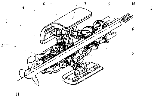
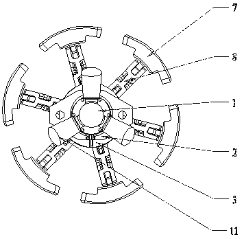
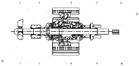
[0023] Embodiment one, combined with the attached Figure 1-3 , a wind power generating set with a variable inertia energy storage flywheel, including a main shaft 1, a main shaft bearing support 2, a flywheel clutch 3, an actuator support 6, an actuator 10, an impeller 11, a generator 12 and a flywheel mechanism, the impeller 11 is installed on one end of the main shaft 1, and the wind energy is converted into the rotational kinetic energy of the main shaft by the impeller; 5. The counterweight 7, the counterweight connecting rod 8 and the counterweight push rod 9, the counterweight 7, the counterweight connecting rod 8, and the counterweight push rod 9 are evenly distributed in the circumferential direction outside the axis of the main shaft 1 ,

[0024] One side of the actuator 10 is fixedly mounted on the actuator support 6, and the other side is axially connected with the flywheel sliding support 5, and does not constrain its circumferential rotation. Under the action o...

Embodiment 2

[0026] Embodiment two, combined with figure 1 And attached Figure 4-5 , the flywheel fixed support 4 is axially fixed and circumferentially rotatably installed on the outer cylindrical surface of the middle section of the main shaft 1, that is, the flywheel fixed support 4 is installed on the outer cylindrical surface of the middle section of the main shaft 1, and can be Rotate relative to the main shaft 1, one side of the flywheel fixed support 4 is fixedly connected with the driven part of the flywheel clutch 3, and the other side is limited by the axial direction of the main shaft 1, so no axial displacement can occur. The flywheel sliding support 5 is mounted on the outer cylindrical surface of the main shaft 1 so as to be slidable in the axial direction and rotatable in the circumferential direction, and can rotate and slide relative to the main shaft 1 .

[0027] The flywheel clutch 3 is installed on the outer cylindrical surface of the middle section of the main shaft...

Embodiment 3

[0030] Embodiment three, combined with the attachedfigure 1 And attached Figure 6-7 , the active part on one side of the flywheel clutch 3 is fixedly installed on the main shaft 1, and rotates synchronously with the main shaft 1, and the driven part on the other side is connected with the fixed support 4 of the flywheel, and can rotate synchronously with the flywheel mechanism; The flywheel clutch 3 has separation, semi-linkage, and linkage states. When the flywheel clutch 3 is in a separate state, the main shaft 1 and the flywheel fixed support 4 are completely disconnected. At this time, the flywheel mechanism does not follow the main shaft at all. 1 rotation; when the flywheel clutch 3 is in a semi-linked state, the main shaft 1 transmits part of the torque to the flywheel mechanism, and the flywheel mechanism and the main shaft 1 rotate asynchronously; when the flywheel clutch 3 is in a linked state , the flywheel mechanism rotates synchronously with the main shaft 1 .

...


PUM


Abstract

The invention discloses a wind turbine generator system with variable inertia energy storage flywheel, including the spindle, Main bearing shaft mount, flywheel clutch, Actuator mount, An actuator, animpeller, a generator and a flywheel mechanism, a flywheel sliding support, comprising a counterweight, a counterweight block connecting rod and a counterweight block pushing rod, wherein the counterweight block, the counterweight block connecting rod and the counterweight block pushing rod are circumferentially uniformly distributed outside the spindle axis, the flywheel fixing support is axially fixed, and the flywheel fixing support is circumferentially rotatably mounted on an outer cylindrical surface of a middle section of the spindle. The invention relates to a wind turbine generator system with variable inertia energy storage flywheel, The beneficial effects are as follows: When the inertia of the flywheel mechanism is suddenly introduced into or removed from the main shaft, the rotation speed of the flywheel mechanism can be reasonably adjusted in the process of energy storage and energy release. When the wind speed is high, the impulse of the main shaft and the fluctuation ofthe rotation speed will not be caused in the process of introducing the flywheel mechanism, and the inertia of the flywheel mechanism can be adjusted steplessly in a certain range.

Description

technical field [0001] The present application relates to the field of wind power generators, in particular to a wind power generator with a variable inertia energy storage flywheel. Background technique [0002] As a clean and renewable energy source, wind energy has huge reserves. The wind power stations currently built are composed of a large number of wind turbines. Each wind turbine converts the kinetic energy of the wind into mechanical energy through the wind wheel, and then generates electricity The machine converts mechanical energy into electrical energy and outputs it to the grid. However, the wind force and wind speed of the natural wind in the wind field are very unstable, and the wind force and wind speed are changing all the time, especially when the wind speed in the wind field is too high, the wind speed is greater than the cut-out wind speed of the wind turbine rotor, If the wind energy captured by the impeller is not reduced through pitch adjustment, it w...

Claims


Application Information

Patent Timeline
Patent Type & Authority Patents(China)
IPC IPC(8): F03D9/12F03D7/00
CPCF03D7/00F05B2260/421F05B2270/101F03D9/12Y02E10/72Y02E60/16Y02E70/30
Inventor 张蔚
Owner CHANGZHOU TEXTILE GARMENT INST
Learn More