Photovoltaic module structure capable of reducing potential cause attenuation effect of photovoltaic module

A photovoltaic module and attenuation effect technology, applied in the field of photovoltaic module structure, can solve problems such as affecting the power generation efficiency of photovoltaic modules and the failure of solar cells

Pending Publication Date: 2018-11-27
JIANGSU LINYANG PHOTOVOLTAIC TECH
View PDF0 Cites 1 Cited by
  • Summary
  • Abstract
  • Description
  • Claims
  • Application Information

AI Technical Summary

Problems solved by technology

[0002] The main reason for the potential attenuation effect of photovoltaic modules is that in the environment of high temperature, high humidity and high voltage of photovoltaic systems, sodium ions in the packaging glass of photovoltaic modules will be precipitated, and the sodium ions of the packaging glass of the

Method used


Image

  • Photovoltaic module structure capable of reducing potential cause attenuation effect of photovoltaic module
  • Photovoltaic module structure capable of reducing potential cause attenuation effect of photovoltaic module
  • Photovoltaic module structure capable of reducing potential cause attenuation effect of photovoltaic module

Examples


Embodiment 1

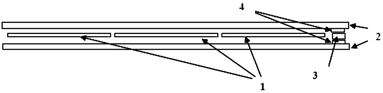
[0025] Example 1: Combining figure 1 , a double-glass module structure that reduces the potential attenuation effect of photovoltaic modules, the upper packaging glass 2, the conductive strip 4, the bus strip 3, the conductive strip 4, and the back plate 5 are sequentially stacked and contacted, and the back plate 5 is the lower packaging glass. The function of the conductive strip 4 is to be closely attached to the upper packaging glass 2 / back plate 5, and has a good adhesion with the glass 2 / back plate 5, and will not cause the conductive strip 4 to contact the upper packaging glass 2 / back plate after a long time. The backplane 5 is delaminated. Silver plating and copper plating are used to attach the conductive strip 4 to the upper packaging glass 2. The position where the conductive strip 4 is attached cannot block the light-receiving surface of the cell 1. The bus strip 3 is a tin-plated copper strip that can be connected to the conductive strip. 4 Well soldered and turn...

Embodiment 2

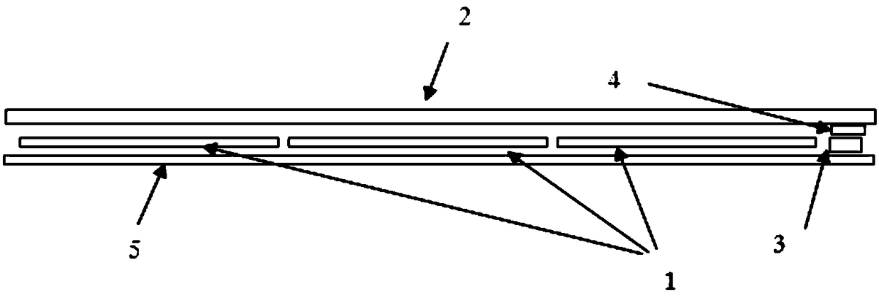
[0026] Example 2: Combining figure 2 , a single-glass module structure that reduces the attenuation effect of potential incentives for photovoltaic modules. The upper packaging glass 2, conductive strips 4, bus strips 3, and backplane 5 are sequentially stacked and contacted, and the backplane 5 is an organic backplane. The function of the conductive strip 4 is that it can be closely attached to the upper packaging glass 2, and has good adhesion with the glass 2, and will not cause delamination of the conductive strip 4 and the upper packaging glass 2 after a long time. Silver plating and copper plating are used to attach the conductive strip 4 to the upper packaging glass 2. The position where the conductive strip 4 is attached cannot block the light-receiving surface of the battery sheet 1. The bus strip 3 is a tin-plated copper strip that can be connected to the conductive strip. 4 Well soldered and turned on.

[0027] In Embodiment 1 and Embodiment 2, the photovoltaic mo...


PUM

PropertyMeasurementUnit
Thicknessaaaaaaaaaa

Abstract

The invention discloses a photovoltaic module structure capable of reducing the potential cause attenuation effect of a photovoltaic module, a battery piece is arranged between an upper-layer packaging glass and a back board, and a bus bar is connected with the battery piece, and is characterized in that the upper-layer packaging glass and the back board are connected and communicated with the busbar. According to the structural scheme, the packaging glass, the bus bar and the battery piece of the photovoltaic module form an equipotential body, and the built-in electric fields of the packaging glass and the battery pieces are eliminated, and under the high-temperature high-humidity high-voltage environment of the photovoltaic system, the sodium ions in the glass are lack of the high electric field up to 1000-1500V, the ability of the sodium ion drift to be attached to the surface of the battery piece is reduced. The photovoltaic module is mainly used for prolonging the service life ofthe photovoltaic module and ensuring that the photovoltaic module can be stably output during the operation process.

Description

technical field [0001] The invention relates to the photovoltaic industry, in particular to a photovoltaic module structure that reduces the potential attenuation effect of the photovoltaic module. Background technique [0002] The main reason for the potential attenuation effect of photovoltaic modules is: the photovoltaic system is in a high-temperature, high-humidity, and high-voltage environment, and the sodium ions in the packaging glass of the photovoltaic module will be precipitated, and the acetate particles of the packaging filling polymer or the packaging filling polymer The moisture absorption dissociates to the solar cells in the package, causing the solar cells to fail and affecting the power generation efficiency of other photovoltaic components. [0003] The way to eliminate this attenuation effect now is: [0004] Solar cell side: [0005] (1) Use the surface oxidation of the silicon wafer after etching to generate a silicon dioxide layer, and use the silic...

Claims


Application Information

Patent Timeline
IPC IPC(8): H01L31/02H01L31/048H02S40/34
CPCH01L31/02H01L31/048H02S40/34Y02E10/50
Inventor 丁齐颀徐硕贤陆飞黄健陈章洋陈景周敏珊卫超原
Owner JIANGSU LINYANG PHOTOVOLTAIC TECH
Why Eureka
Try Eureka