High-power microwave mode-conversion antenna based on diffraction period structure

A high-power microwave, periodic structure technology, applied in the direction of radiating element structure, individually energized antenna arrays, antenna combinations with different interactions, etc., can solve problems such as limited application range, large axis angle, dielectric loss, etc. Achieving the effects of wide application fields, improved power capacity and simple structure

Inactive Publication Date: 2018-11-27
UNIV OF ELECTRONICS SCI & TECH OF CHINA
View PDF8 Cites 9 Cited by
  • Summary
  • Abstract
  • Description
  • Claims
  • Application Information

AI Technical Summary

Problems solved by technology

However, the radiation direction of the above-mentioned Vlasov mode conversion antenna changes with the frequency, and the angle with the axis is relatively large, which cannot meet the requirement that the microwave output is still along the axis, and the application range is limited.
[0005] In 2017, Zhao Jianing and others proposed in the patent "A New Type of Mode Switching Antenna Based on Planar Structure" (Application No.: CN201710219562.9, Application Date: 2017.04.06, Application Publication Date: 2017...

Method used


Image

  • High-power microwave mode-conversion antenna based on diffraction period structure
  • High-power microwave mode-conversion antenna based on diffraction period structure
  • High-power microwave mode-conversion antenna based on diffraction period structure

Examples


Embodiment Construction

[0027] In order to better illustrate the purpose, advantages and technical solutions of the present invention, the present invention will be further elaborated below in conjunction with specific examples. It should be noted that the specific implementation examples given below are only for the purpose of explaining and illustrating the present invention in detail, and are not intended to limit the present invention.

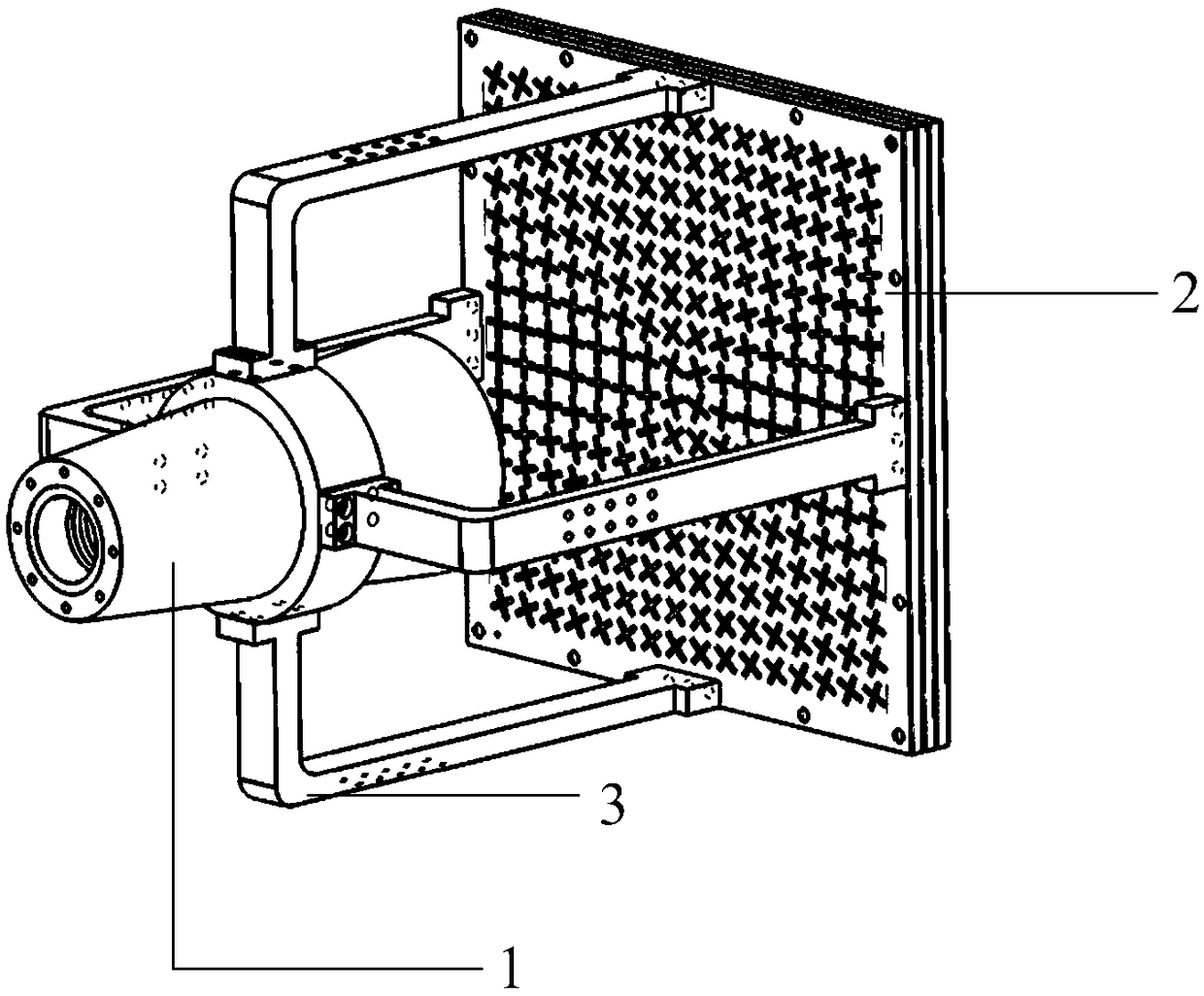
[0028] This embodiment is a kind of TM 01 A high-power microwave mode-to-mode antenna based on a diffraction periodic structure that converts the mode into a single linear polarization mode. The overall structure is shown in figure 1 As shown, the antenna is composed of a primary feed 1, an antenna array 2 and a support 3, and the primary feed is TM 01 The mode exciter, with an exciter diameter of 80mm, is set directly above the antenna front 2 through the bracket 3, and feeds the antenna front in a feed-forward manner. The antenna front is composed of 256 tran...


PUM


Abstract

The invention discloses a high-power microwave mode-conversion antenna based on a diffraction period structure and belongs to the technical field of microwave antennas. The antenna is composed of a primary feed source and an antenna array surface, wherein the primary feed source is a mode exciter capable of generating a symmetrical mode of a rotary shaft and the antenna array surface is subjectedto feeding by adopting a positive feedback manner; the antenna array surface is formed by periodically arraying a plurality of transmitting units formed by overlapping a plurality of layers of slottedmetal thin plates up and down. According to the antenna disclosed by the invention, the metal thin plates with slotted lines are used as the antenna array surface; compared with a traditional microstrip array antenna, the antenna has the advantage that the power capacity is greatly improved; the symmetrical mode of any rotary shaft can be converted into a single linear polarization mode, so thatthe antenna has a wide application field; the antenna also has the advantages of high gains, low sections, simple structure, easiness for processing and the like.

Description

technical field [0001] The invention belongs to the technical field of microwave antennas, in particular to a high-power microwave mode-to-mode antenna based on a diffraction periodic structure. Background technique [0002] High-power microwave refers to electromagnetic waves whose pulse peak power is above 100MW and frequency is in the range of 0.5-300GHz. Due to its own remarkable characteristics and advantages, high-power microwave technology has developed rapidly in recent years. fields are showing great promise. The high power microwave source is one of the core devices in the high power microwave system. Most high-power microwave sources have rotationally symmetric output structures, so the modes they generate are mostly rotationally axisymmetric. For example, relativistic klystrons with coaxial extraction output coaxial TEM modes, while relativistic return wave tubes with axial extraction output circular waveguide TM 01 mold. Either TEM or TM 01 Mode, because th...

Claims


Application Information

Patent Timeline
IPC IPC(8): H01Q1/36H01Q21/22H01Q21/29H01Q15/24
Inventor 李浩杨晓光赵加宁李天明胡标
Owner UNIV OF ELECTRONICS SCI & TECH OF CHINA
Why Eureka
Try Eureka