High-reliability big-work-range sensing energy taking device based on adjustable impedance and regulation and control method

A technology of working range and inductive energy harvesting, which is applied in the direction of circuit devices, battery circuit devices, inductors, etc., can solve the adverse effects of battery life limitation, excessive current, application range of energy harvesting devices, cost and operational reliability, etc. problems, to achieve the effect of large working range, high reliability working range, high reliability and working range

Active Publication Date: 2018-11-27
杨勇
View PDF7 Cites 10 Cited by
  • Summary
  • Abstract
  • Description
  • Claims
  • Application Information

AI Technical Summary

Problems solved by technology

[0010] 2. When the current on the primary side is too large, that is: greater than the upper threshold, the magnetic circuit of the energy harvesting CT is saturated at this time, and cannot provide stable energy for the secondary side
But at the same time, it also brings many unfavorable factors such as large iron core volume, frequent battery charging and discharging, battery life limit, etc., which adversely affects the application range, cost and operation reliability of the entire energy harvesting device.

Method used


Image

  • High-reliability big-work-range sensing energy taking device based on adjustable impedance and regulation and control method
  • High-reliability big-work-range sensing energy taking device based on adjustable impedance and regulation and control method
  • High-reliability big-work-range sensing energy taking device based on adjustable impedance and regulation and control method

Examples


Embodiment Construction

[0070] Specific embodiments of the present invention will be described in detail below in conjunction with the accompanying drawings.

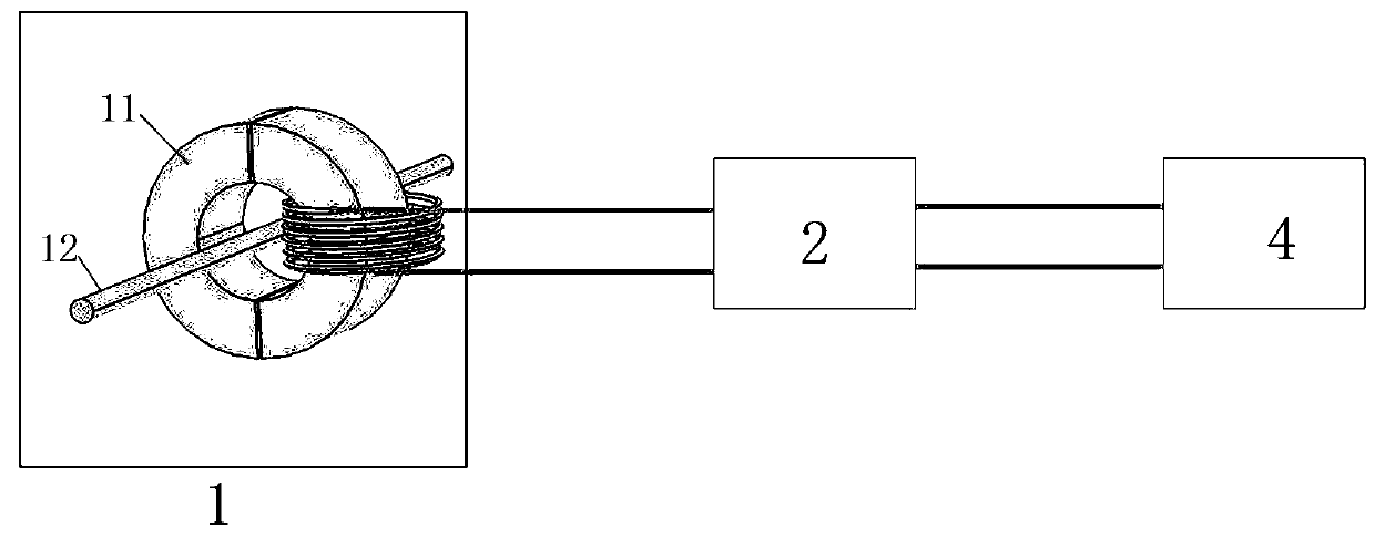
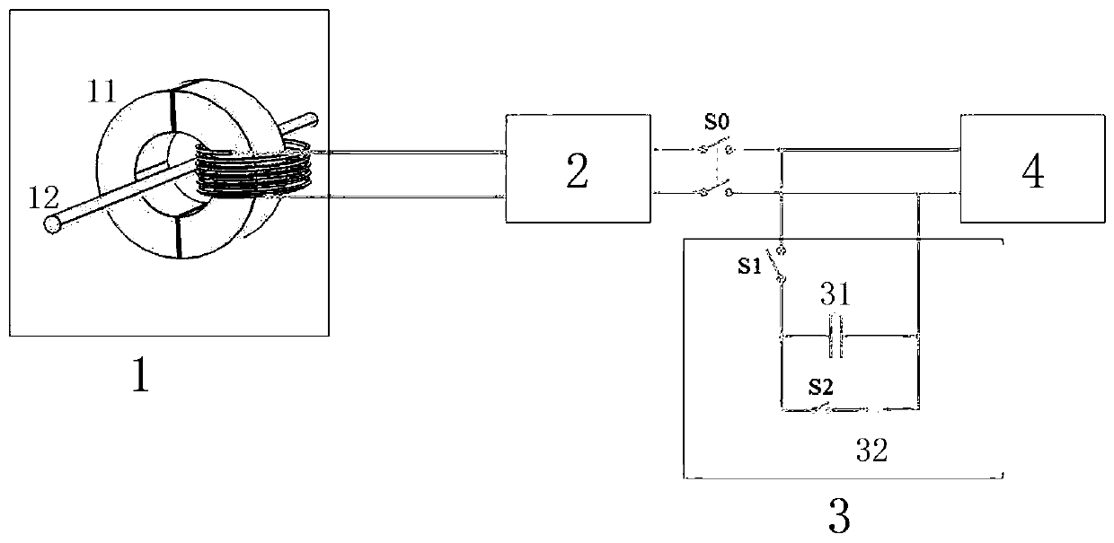
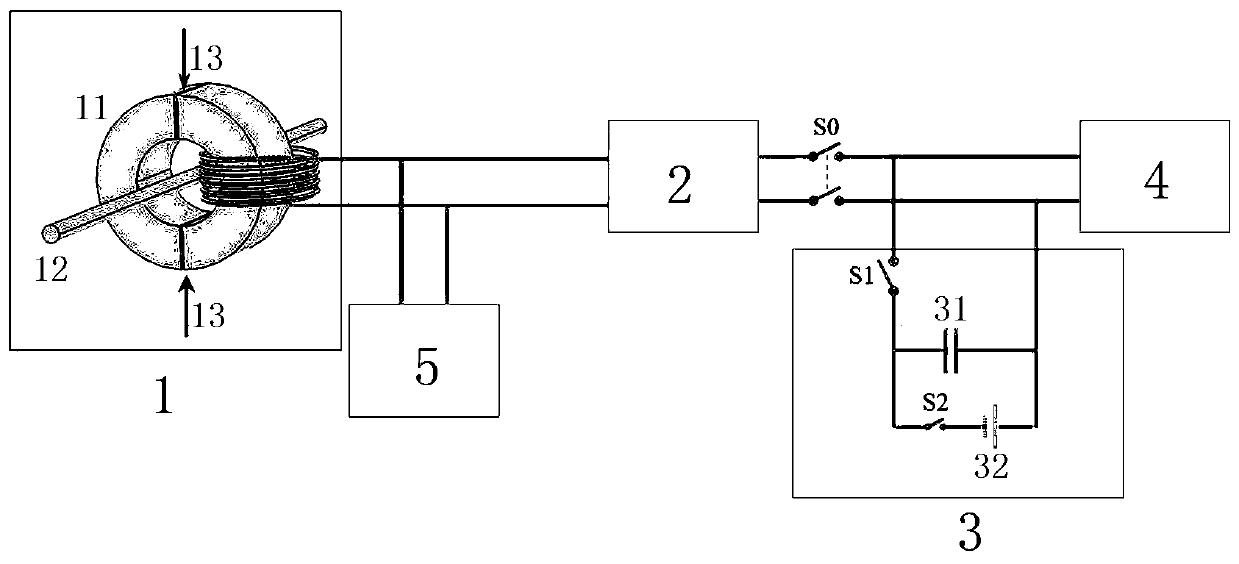
[0071] A high-reliability and large-working-range induction energy-harvesting device based on adjustable impedance, the device includes an energy-harvesting current transformer (energy-harvesting CT), an adjustable impedance circuit, an AC-DC conversion circuit, and has the energy of a storage battery and a supercapacitor Management module and power load. Such as Figure 3a As shown, the secondary side of the energy harvesting CT 1 is connected to the electric load 4 through the AC / DC conversion circuit 2, the energy management module 3 is connected in parallel on the electric load 4 side, and the secondary side of the energy harvesting CT 1 is connected in parallel with the adjustable impedance circuit 5 .

[0072] The adjustable impedance circuit 5 adopts a single-phase full-bridge voltage PWM rectifier or a single-phase full-bridge curren...


PUM


Abstract

The invention provides a high-reliability big-work-range sensing energy taking device based on adjustable impedance. The device comprises an energy taking current transformer (energy taking CT), an adjustable impedance circuit, an AC-DC conversion circuit, a storage battery and a supercapacitor energy management module and an electricity use load. By studying the influence of the secondary side load on the energy taking effect, the mathematical relationship of the active power output by the energy taking CT and the secondary side impedance is built. A method of connecting the adjustable impedance at the secondary side in parallel is used; the obtaining of the required power output when the primary side current changes in a large range is realized through regulating the adjustable impedance. Through a parallel connection resonance mode, the energy CT primary side current threshold value lower limit is reduced; the primary side current threshold value upper limit is improved in an adjustable impedance flow division mode, so that the work range of the energy taking CT can be expanded. The output of the required target power under the condition of large-range fluctuation of the primaryside current of the energy taking CT can be realized according to the mathematical relationship between the output power and the secondary side impedance.

Description

technical field [0001] The invention relates to the technical field of power supply applied to an on-line monitoring system of a transmission line, in particular to an adjustable impedance-based high-reliability and large-working-range induction energy harvesting device and a control method. Background technique [0002] With the rapid development of smart grids, the voltage level and transmission capacity of power system transmission lines are constantly improving. On-line monitoring of the operating status of high-voltage transmission lines and accurate positioning of line faults have attracted more and more attention. In a high-voltage, strong electromagnetic environment, a stable and reliable power supply is the premise and basis for the long-term stable operation of the online monitoring device. [0003] In recent years, Chinese and foreign scholars have conducted a large number of fruitful researches on the power supply of transmission line on-line monitoring devices. ...

Claims


Application Information

Patent Timeline
IPC IPC(8): H02J7/06H01F38/30
CPCH02J2007/10H01F38/30H01F2038/305H02J7/06
Inventor 辛帅魁陈锋尹霖
Owner 杨勇
Why Eureka
Try Eureka