Thermal spraying combined manufacturing process of lost foam cast ductile iron pipe fittings

A technology of ductile iron pipe and lost foam casting, which is applied in the field of foundry engineering, and can solve problems such as uneven coating, easy falling off of paint, and affecting the quality and quality of finished products, so as to avoid falling blocks, prevent sand sticking, and ensure quality and quality effects

Active Publication Date: 2018-11-30
SICHUAN CHUANJIAN PIPES
View PDF3 Cites 1 Cited by
  • Summary
  • Abstract
  • Description
  • Claims
  • Application Information

AI Technical Summary

Problems solved by technology

[0006] The present invention aims to provide a manufacturing process of lost foam casting nodular cast iron pipe fittings combined with thermal spraying, which combines thermal spraying to enhance the strength and smoothness of the coating layer, and solves the problem that the coating is easy to fall off and the coating is uneven. Finished product quality and quality issues

Method used


Image

  • Thermal spraying combined manufacturing process of lost foam cast ductile iron pipe fittings

Examples


Embodiment 1

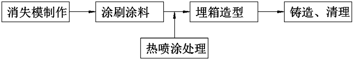
[0022] Embodiment one: if figure 1 As shown, the present invention provides a kind of manufacturing process of the lost foam casting ductile iron pipe fittings combined with thermal spraying, comprising the following steps:

[0023] a. Production of lost foam: make foam plastic into a real mold corresponding to the part structure and size of ductile iron pipe fittings;

[0024] b. Brushing paint: Assembling and drying the solid mold, coating the combined solid mold with anti-high temperature paint, and then drying the coating of the solid mold;

[0025] c. Thermal spraying treatment: thermal spraying treatment is carried out on the surface of the paint, the temperature of thermal spraying is 60-150°C, and the thickness of the thermal spraying material is not more than 1mm;

[0026] d. Buried box modeling: bury the solid mold in the sand box after the thermal spraying operation is completed;

[0027] e. Casting and cleaning: The metal liquid is poured under negative pressure ...

Embodiment 2

[0031] In order to make the effect of thermal spraying better, in step c in embodiment 1, the temperature of thermal spraying is 60-150°C.

Embodiment 3

[0033] In order to further optimize the flatness of the mold and ensure the quality of the finished product, the relationship between the size L model of the lost foam casting model in Example 1 and the size L cast iron pipe fitting of the nodular cast iron pipe fitting is:

[0034] L 模型 =L 铸铁管件 ×(1+1.5%)

[0035] Since the molten metal will shrink after cooling, by setting a shrinkage rate of 1.5%, it is ensured that the size of the ductile iron pipe fitting does not deviate in actual use.


PUM

PropertyMeasurementUnit
thicknessaaaaaaaaaa

Abstract

The invention discloses a thermal spraying combined manufacturing process of lost foam cast ductile iron pipe fittings. The thermal spraying combined manufacturing process comprises the following steps that a, lost foam is manufactured, specifically, foamed plastic is manufactured into real molds corresponding to the ductile iron pipe fittings in part structure and size; b, coating brushing is conducted, specifically, the real molds are assembled, combined and dried, the combined real molds are brushed with high-temperature preventing coating, and then the coating of the real molds is dried; c, thermal spraying treatment is conducted, specifically, the surface layer of the coating is subjected to thermal spraying treatment, the thermal spraying temperature is 50-250 DEG C, and the thickness of a thermal spraying material is no more than 1 mm; d, burying-in-box and modeling are conducted, specifically, the real molds subjected to thermal spraying operation are buried in a sand box and modeled; and e, casting and clearing are conducted, specifically, molten metal is poured into the sand box at the negative pressure, cooling, shot blasting, polishing clearing and a pressure test are conducted, and then finished products are obtained. The strength and flatness of a coating layer are improved through combination of thermal spraying, and the problem that the coating is likely to falloff, brushing is nonuniform, and consequently, the quality of the finished products is affected is well solved.

Description

technical field [0001] The invention relates to the technical field of casting engineering, in particular to a manufacturing process of a lost foam casting ductile iron pipe fitting combined with thermal spraying. Background technique [0002] The nodular cast iron pipe is made by adding magnesium or rare earth magnesium combined with gold nodularizing agent to the molten iron before pouring to spheroidize graphite and reduce stress concentration, so that the pipe has high strength, high elongation, impact resistance, corrosion resistance, good sealing, etc. Advantages of pipe fittings; the inner wall is lined with cement mortar, which improves the water delivery environment of the pipeline, increases the water supply capacity, and reduces energy consumption; the nozzle adopts a flexible interface, and the pipe itself has a large elongation rate, which makes the pipeline more flexible. In the buried pipeline, it can work together with the soil around the pipeline to improve ...

Claims


Application Information

Patent Timeline
Patent Type & Authority Applications(China)
IPC IPC(8): B22C9/04B22C9/12B22C23/02
CPCB22C9/04B22C9/12B22C23/02
Inventor 唐宇许顺刘杲鲜其祥
Owner SICHUAN CHUANJIAN PIPES
Why Eureka
Try Eureka