
Magneto-controlled sputter coating production line

A magnetron sputtering coating and production line technology, which is applied in sputtering coating, ion implantation coating, vacuum evaporation coating, etc., can solve problems such as difficulty in stabilizing the sputtering environment atmosphere, easy occurrence of pinholes, and performance differences. Achieve the effect of high infrared absorption/reflectivity and good heat insulation

Pending Publication Date: 2018-11-30
FOSHAN JUSHITAI POWDER METALLURGY CO LTD
View PDF7 Cites 4 Cited by
  • Summary
  • Abstract
  • Description
  • Claims
  • Application Information

AI Technical Summary

Problems solved by technology

Among them, the single-vacuum coating machine has the advantages of simple structure and low price. Since this coating machine adopts a single-cycle coating production method, the vacuum chamber needs to be degassed and vacuumized every time the coating production process is completed, and the sputtering environment atmosphere is difficult. Stable, coating quality is not guaranteed, low efficiency
Single machine with multiple operations, it is difficult to achieve consistent equipment status and requires multiple people to operate, which can easily cause performance differences
The step-by-step method has low production capacity, high unit cost, and is prone to pinholes, white spots and other coating defects

Method used


Image

  • Magneto-controlled sputter coating production line
  • Magneto-controlled sputter coating production line
  • Magneto-controlled sputter coating production line

Examples


Embodiment Construction

[0028] In order to fully understand the technical content of the present invention, the technical solutions of the present invention will be further introduced and illustrated below in conjunction with specific examples, but not limited thereto.

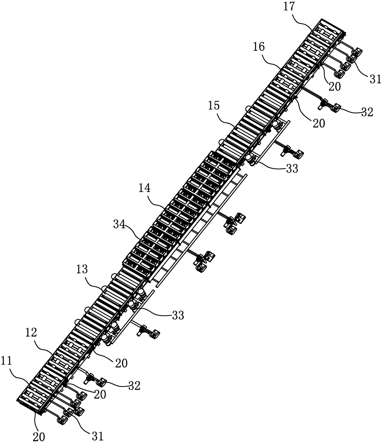
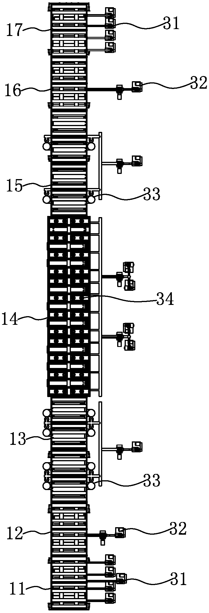
[0029] Such as Figure 1 to Figure 10 It is a drawing of an embodiment of the present invention.

[0030] A magnetron sputtering coating production line, such as Figure 1 to Figure 5 As shown, it includes a vertical vacuum chamber 10, and the vertical vacuum chamber 10 includes a film feed chamber 11, a film feed buffer chamber 12 located at the discharge end of the film feed chamber 11, and a film feed transition located at the discharge end of the film feed buffer chamber 12. Chamber 13, the coating chamber 14 that is located at the discharge end of the transition chamber 13, the transition chamber 15 that is located at the discharge end of the coating chamber 14, the buffer chamber 16 that is located at the discharge end of the ...


PUM

PropertyMeasurementUnit
thicknessaaaaaaaaaa

Abstract

The invention relates to a magneto-controlled sputter coating production line. The production line comprises a chip input chamber, chip input buffering chambers arranged at the discharging end of thechip input chamber, a chip input transition chamber arranged at the discharging ends of the chip input buffering chambers, coating chambers arranged at the discharging end of the chip input transitionchamber, a chip output transition chamber arranged at the discharging ends of the coating chambers, chip output buffering chambers arranged at the discharging end of the chip output transition chamber, and a chip output chamber arranged at the discharging ends of the chip output buffering chambers. A plurality of coating chambers are arranged. A plurality of cathode rotating target positions anddirect current plane target positions are arranged in each coating chamber. According to the magneto-controlled sputter coating production line, the products which have good heat-insulating, energy-saving and weatherproof properties, can meet high absorption / reflection rates of infrared rays at the same time, and can achieve high penetration of visible light and high barrier of ultraviolet rays are obtained, and energy-saving modified glass for building can also be produced.

Description

technical field [0001] The invention relates to coating equipment, more specifically to a magnetron sputtering coating production line. Background technique [0002] Magnetron sputtering coating is a coating method commonly used at present. Domestic magnetron sputtering coating equipment is divided into single-sided cathode sputtering target design and single intermediate frequency cathode sputtering or single DC cathode sputtering. Not only the production capacity of the equipment is low and the production cost is high, but also the process product is single and the product quality is unstable. The temperature inside the current magnetron sputtering chamber is uneven and unstable, which will not only affect the characteristics of the film layer but also increase the fragmentation rate of the product, resulting in a low production yield. [0003] At present, the vacuum coating machines used to manufacture solar selective absorption coatings include single vacuum chamber coa...

Claims


Application Information

Patent Timeline
Patent Type & Authority Applications(China)
IPC IPC(8): C23C14/35C23C14/56C23C14/54
CPCC23C14/352C23C14/545C23C14/568
Inventor 崔明培余力韩金保龙甫强苏龙庆邝耀庭刘思敏
Owner FOSHAN JUSHITAI POWDER METALLURGY CO LTD
Learn More