
Shallow cold energy cyclic cooling dehumidification and waste heat utilization system for mine tunneling roadway

A technology of circulating cooling, cooling and dehumidification, which is applied in the ventilation of mines/tunnels, mining equipment, earth-moving drilling, etc. It can solve the problems of long transportation distance, secondary heat damage and high energy consumption of cold carriers.

Inactive Publication Date: 2018-11-30
BEIJING UNIVERSITY OF CIVIL ENGINEERING AND ARCHITECTURE +2
View PDF5 Cites 2 Cited by
  • Summary
  • Abstract
  • Description
  • Claims
  • Application Information

AI Technical Summary

Problems solved by technology

Especially in high-temperature and high-humidity mining layers, the continuous high-temperature and high-humidity operating environment has a great impact on operators and related equipment, which not only affects work efficiency, but also increases the downhole accident rate
[0003] In order to improve the downhole working environment, at present, the cooling and dehumidification operation of the downhole working environment is usually carried out by means of centralized cooling on the well. The energy consumption is high because of the cooling capacity generated, and the carrier of the cooling capacity (such as frozen water, ice cube / slurry, etc.) has a long transportation distance from the well to the downhole, so there is a large loss of cooling capacity
On the other hand, since the working environment is located underground, it is difficult to discharge the condensation heat generated by local cooling, which may easily lead to secondary heat damage.
In addition, since the current cooling method targets the entire working area, such a cooling treatment method has the problem of high energy consumption
Therefore, the current effect of cooling and dehumidification needs to be further improved.

Method used


Image

  • Shallow cold energy cyclic cooling dehumidification and waste heat utilization system for mine tunneling roadway
  • Shallow cold energy cyclic cooling dehumidification and waste heat utilization system for mine tunneling roadway
  • Shallow cold energy cyclic cooling dehumidification and waste heat utilization system for mine tunneling roadway

Examples


Embodiment Construction

[0025]Various exemplary embodiments, features, and aspects of the invention will be described in detail below with reference to the accompanying drawings. The same reference numbers in the figures indicate functionally identical or similar elements. While various aspects of the embodiments are shown in drawings, the drawings are not necessarily drawn to scale unless specifically indicated.

[0026] The word "exemplary" is used exclusively herein to mean "serving as an example, embodiment, or illustration." Any embodiment described herein as "exemplary" is not necessarily to be construed as superior or better than other embodiments.

[0027] It should be noted that, in the description of the present invention, unless otherwise clearly stipulated and limited, the terms "installation", "connection", and "connection" should be understood in a broad sense, for example, it can be a fixed connection or a detachable connection. Connected, or integrally connected; it can be mechanica...


PUM


Abstract

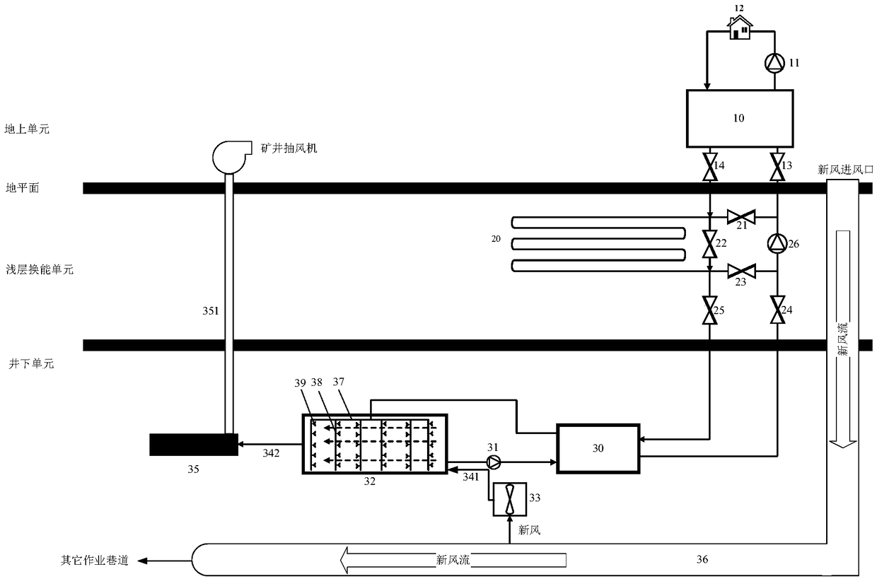
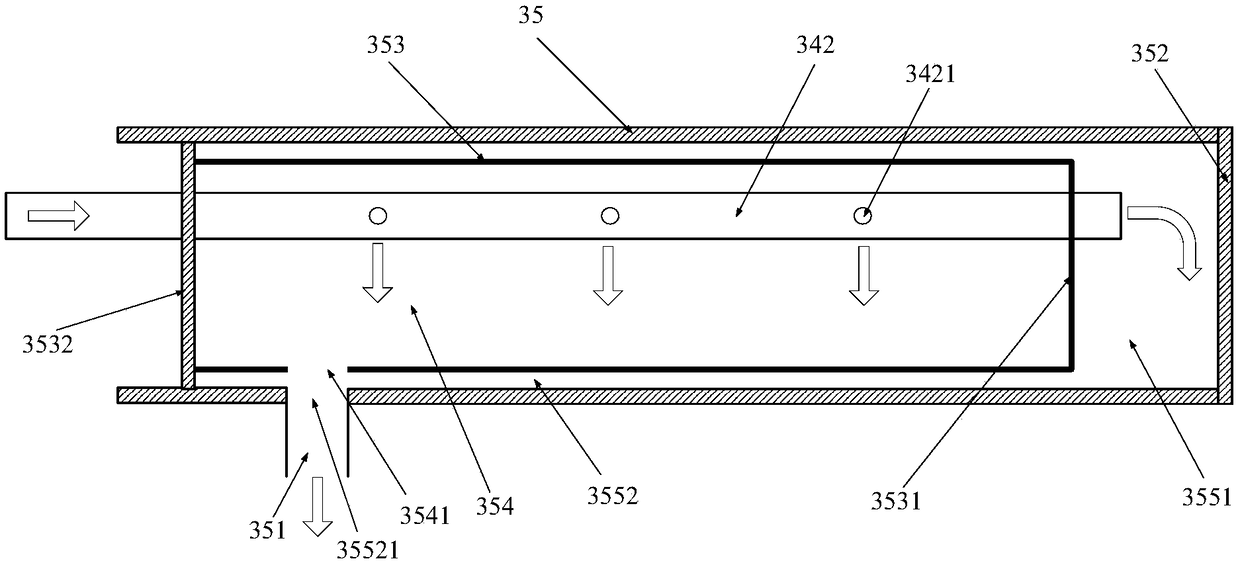
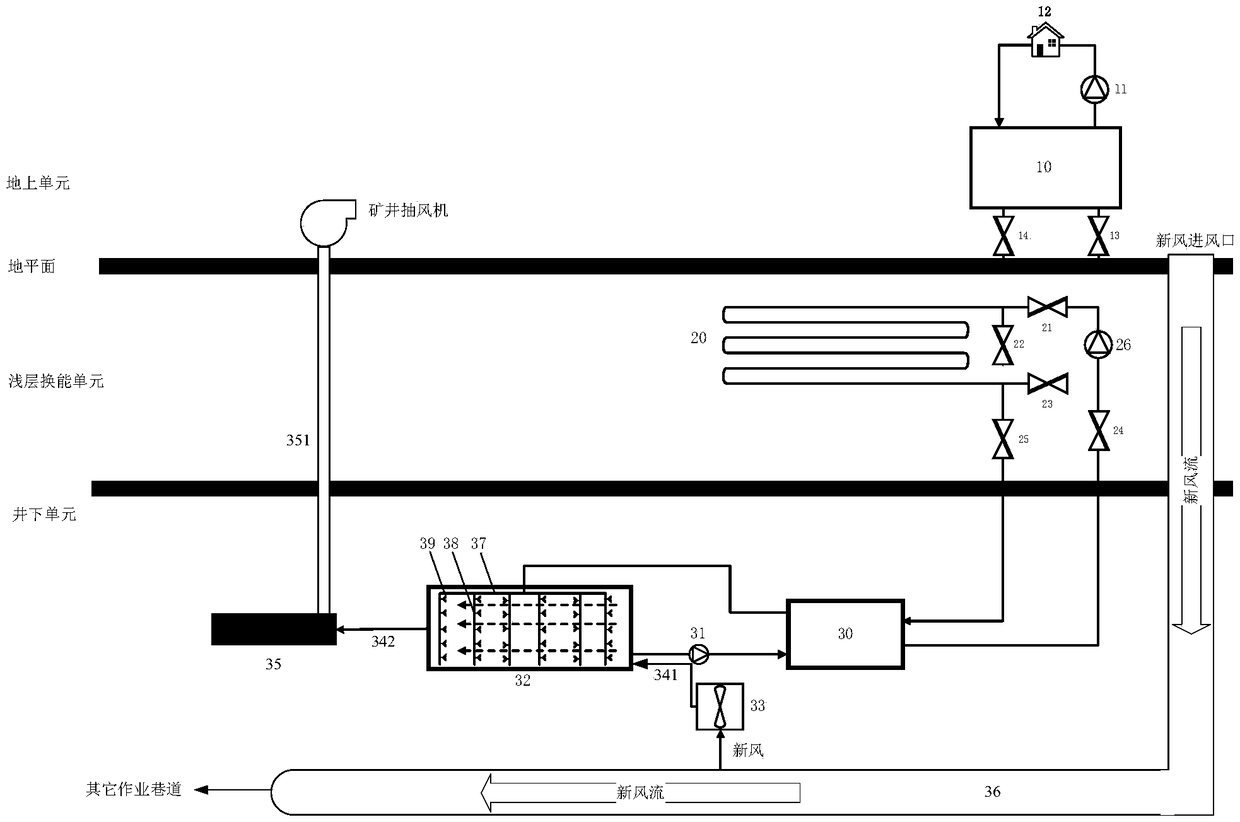
The embodiment of the invention provides a shallow cold energy cyclic cooling dehumidification and waste heat utilization system for a mine tunneling roadway. The tunneling roadway is provided with atunneling working face, the shallow cold energy cyclic cooling dehumidification and waste heat utilization system comprises an isolating body of a cylindrical structure, an overground unit, a shallowenergy exchange unit and a downhole unit; the isolating body is arranged in the tunneling roadway; the overground unit, the shallow energy exchange unit and the downhole unit are distributed from topto bottom and can communicate; the cylindrical structure divides the tunneling roadway into an inner roadway and an outer roadway which communicate with the downhole unit respectively; the overgroundunit comprises a heat pump unit, and the evaporation side of the heat pump unit is configured with a first valve and a second valve; and the shallow energy exchange unit comprises a transducer buriedin an underground soil layer, and the transducer is configured with a valve set. According to the shallow cold energy cyclic cooling dehumidification and waste heat utilization system for the mine tunneling roadway, on the one hand, the cooling dehumidification effect of the tunneling roadway is ensured, and on the other hand, full utilization of energy is achieved.

Description

technical field [0001] The invention relates to the technical field of cooling and dehumidification in high-temperature mines, in particular to a shallow cold energy cycle cooling and dehumidification and waste heat utilization system for mine excavation roadways. Background technique [0002] With the continuous increase of mine mining depth, the temperature of mine rock formations continues to rise, so the underground heat damage becomes more and more serious. Especially in high-temperature and high-humidity mining layers, the continuous high-temperature and high-humidity operating environment has a great impact on operators and related equipment, which not only affects work efficiency, but also increases the downhole accident rate. [0003] In order to improve the downhole working environment, at present, the cooling and dehumidification operation of the downhole working environment is usually carried out by means of centralized cooling on the well. The energy consumptio...

Claims


Application Information

Patent Timeline
IPC IPC(8): E21F3/00
CPCE21F3/00
Inventor 熊亚选郝思逸何敏徐鹏陈红兵
Owner BEIJING UNIVERSITY OF CIVIL ENGINEERING AND ARCHITECTURE
Learn More