
Closed-loop control system and control method of unmanned aerial vehicle

A closed-loop control, unmanned aerial vehicle technology, applied in the control/regulation system, attitude control, non-electric variable control and other directions, can solve the problems of high power consumption, high cost, error-prone distance judgment, etc., to achieve ranging and positioning accuracy High, algorithmically simple effect

Inactive Publication Date: 2018-11-30
上海天豚信息科技有限公司
View PDF6 Cites 2 Cited by
  • Summary
  • Abstract
  • Description
  • Claims
  • Application Information

AI Technical Summary

Problems solved by technology

[0006] The problem solved by the present invention is that in the existing technologies for precise positioning of UAVs in indoor scenes, the cost of technologies such as SLAM using cameras, laser radars, and various sensor fusion technologies is relatively high, and compared with the airborne load of UAVs It is too heavy and consumes a lot of power, and the way of using ultrasonic waves is easily disturbed by the environment. Ultrasonic multi-path and diffraction will lead to error-prone distance judgments

Method used


Image

  • Closed-loop control system and control method of unmanned aerial vehicle
  • Closed-loop control system and control method of unmanned aerial vehicle

Examples


Embodiment 1

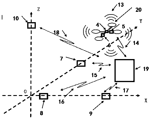
[0056] Such as figure 1 Shown is a schematic diagram of the space three-dimensional coordinate system O-XYZ and the UAV closed-loop control system constructed in the embodiment of the present invention. refer to figure 1 , in the space three-dimensional coordinate system O-XYZ and the illustration labels in the UAV closed-loop control system are as follows:

[0057] The three-dimensional coordinate system O-XYZ of the space, where O is the origin of the coordinate system;

[0058] Labels 4, 5, 6: acoustic wave emitters;

[0059] Labels 7, 8, 9, 10: acoustic wave receivers;

[0060] Label 13: acoustic signal;

[0061] Label 14: synchronous command signal (that is, electromagnetic wave signal);

[0062] Labels 15, 16, 17, 18: information channels between the closed-loop control system processor and each acoustic wave receiver;

[0063] Label 19: Closed-loop control system processor;

[0064] Label 20: UAV.

[0065] In this embodiment, the UAV closed-loop control system i...

Embodiment 2

[0082] The inventor further studies that the flight controller of the UAV mainly includes: sensors such as accelerometers, gyroscopes, and magnetometers, and real-time processors. Its function is to measure and control the flight attitude of the UAV. Therefore, the inventor considers whether The function of the flight controller can be replaced by other means.

[0083] Specifically, by arranging multiple acoustic wave transmitters on different parts of the airborne platform of the UAV 20, multiple acoustic wave transmitters can transmit acoustic wave signals in a time-division multiplexed or frequency-division multiplexed manner. The positioning process of Embodiment 1 locates the respective coordinate positions of each sound wave emitter, and then calculates the real-time attitude and real-time position of the UAV during flight according to the relative positional relationship between a plurality of sound wave emitters and the UAV body (that is, The center position coordinate...


PUM


Abstract

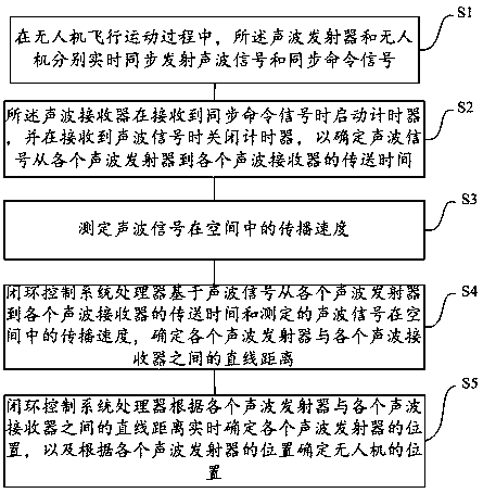
The invention discloses a closed-loop control system and control method of an unmanned aerial vehicle. In the process of flying, the unmanned aerial vehicle synchronously sends synchronous command signals when sending sound wave signals, time of the synchronous command signals received by various sound wave receivers is used as the sending time of the sound wave signals, and after the sound wave receivers receive the sound wave signals, the transmission time of the sound wave signals from sound wave emitters to the sound wave receivers is determined. By combining measured propagation speed ofthe sound wave signals in a space, straight-line distances between the sound wave emitters and the sound wave receivers are obtained, and thus the positions of the sound wave emitters are determined and the unmanned aerial vehicle is located. The positions of the unmanned aerial vehicle obtained in real time are further used as feedback quantities which is compared with preset tracks to obtain dynamic error amounts, remote control commands are amended, and through the process of repeated iterations, the dynamic error amounts are further shrunken to complete the closed-loop control of the unmanned aerial vehicle. The closed-loop control system and control method of the unmanned aerial vehicle have simple algorithm, no multipath interference, and higher ranging and location accuracy.

Description

technical field [0001] The invention relates to the technical field of unmanned aerial vehicle control, in particular to a closed-loop control system and control method for an unmanned aerial vehicle. Background technique [0002] Multi-rotor UAV is a short-distance aircraft that has gradually become popular in recent years. It is widely used in unmanned operation scenarios such as aerial photography, inspection, and express delivery. In these application scenarios, UAVs mostly fly in outdoor spaces. In order to keep the flight trajectory of UAVs consistent with the preset flight path, it is usually necessary to locate the spatial position of UAVs and perform remote control. Outdoor space flight positioning technology usually uses GPS (Global Positioning System) / Beidou and other satellite navigation and positioning methods, and cooperates with the drone's own barometer, camera and other sensors to achieve more accurate positioning. In other indoor application scenarios, U...

Claims


Application Information

Patent Timeline
Patent Type & Authority Applications(China)
IPC IPC(8): G05D1/08G05D1/10
CPCG05D1/0808G05D1/101
Inventor 姚思聪其他发明人请求不公开姓名
Owner 上海天豚信息科技有限公司
Learn More