Constant-pressure water pumping compressed gas energy storage system and energy storage method

A compressed air energy storage, water gas technology, applied in the direction of hydroelectric power generation, steam engine devices, engine components, etc., can solve the huge investment cost of high-pressure gas storage tanks, accelerate the corrosion of water and gas co-containment tanks, reduce the safety of co-containment tanks, etc. problems, to achieve the effect of improving system operation economy, shortening payback period, and improving system efficiency and economy

Active Publication Date: 2018-12-04
XI AN JIAOTONG UNIV
View PDF5 Cites 21 Cited by
  • Summary
  • Abstract
  • Description
  • Claims
  • Application Information

AI Technical Summary

Problems solved by technology

However, the higher temperature of water vapor will reduce the safety of the compatible tank to a certain extent, and will accelerate the corrosion of the water-gas compatible tank
The prior art water-air co-containment cabin electric energy storage system with constant pressure of high-pressure gas storage tank (CN201410312066.4), in the process of energy storage, the air is transferred from the water-gas co-containment cabin to the high-pressure gas storage tank through the supercharger , during the energy release process, the air in the high-pressure air storage chamber is reduced to a fixed pressure by the pressure-stabilizing valve and then enters the water-air coexistence chamber to achieve the purpose of maintaining a constant pres

Method used


Image

  • Constant-pressure water pumping compressed gas energy storage system and energy storage method

Examples


Embodiment Construction

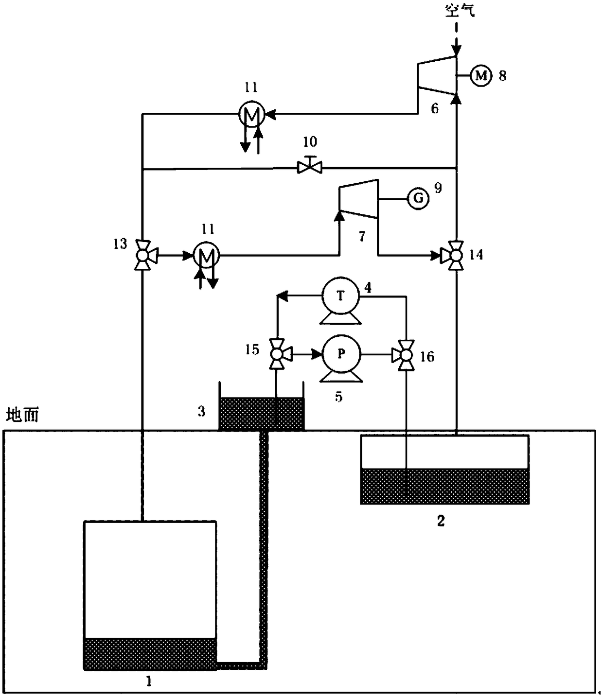
[0027] The present invention is described in further detail below in conjunction with accompanying drawing:

[0028] Such as figure 1 As shown, a constant-pressure air storage pumping compressed air energy storage system includes a high-pressure constant-pressure air storage cabin 1, a water-gas co-containment cabin 2 and a water storage tank 3, and the water storage tank 3 is higher than the high-pressure constant-pressure air storage cabin 1 and the water-gas co-containment cabin 2, the water outlet at the bottom of the reservoir 3 is connected to the bottom water outlet of the high-pressure constant-pressure gas storage cabin 1, and a water turbine 4 and a water pump 5 are arranged between the reservoir 3 and the water-gas co-containment cabin 2, The water inlet of the water turbine 4 and the water outlet of the water pump 5 are connected to the bottom of the water-gas co-containment cabin 2, the water outlet of the water turbine 4 and the water inlet of the water pump 5 ar...


PUM


Abstract

The invention discloses a constant-pressure gas storage water pumping compressed gas energy storage system and an energy storage method. A high-pressure constant-pressure gas storage cabin, a water-gas jointly containing cabin and a water storage pool are arranged, stable sealing pressure is provided through the water-level difference of the high-position water storage pool and the low-position high-pressure constant-pressure gas storage cabin, the investment cost of the system is greatly reduced, the recovering age limit of the energy storage system is shortened, the operating economy of thesystem is improved, the energy loss in the throttling pressure stabilizing process is avoided, it is guaranteed that a compressor and an expansion machine run under the constant working condition, thesystem efficiency is improved, the water-gas jointly containing cabin and the water storage pool form a water pumping energy storage system, the high-pressure constant-pressure gas storage cabin anda water storage pool close to the ground form a water pumping energy storage system, that is the double water pumping energy storage systems are formed, in the energy storage process and the energy releasing process, flowing changing speeds of water in the water storage pool and water in the low-position high-pressure gas storage cabin are slow, the loss of the water in the flowing process is relatively small, and the efficiency of the water pumping energy storage system formed by the high-pressure constant-pressure gas storage cabin and the water storage pool close to the ground is improved.

Description

technical field [0001] The invention relates to the field of physical storage of electrical energy, in particular to a constant-pressure pumped compressed gas energy storage system and an energy storage method. Background technique [0002] Energy is the driving force for social development. With the increasingly prominent energy and environmental problems, renewable energy such as wind energy and solar energy has received more and more attention. Insufficient capacity and other issues have brought great challenges to the development of renewable energy. As a transitional system between the power plant and the grid, the energy storage system can effectively solve the grid connection problem of renewable energy. In addition, the energy storage system can also smooth the load fluctuation of the power grid and improve the security and controllability of the power grid. Among the existing energy storage methods, due to the limitation of energy storage scale, discharge time, te...

Claims


Application Information

Patent Timeline
IPC IPC(8): F03B13/06F01K23/00F01K27/00F01K13/00F01K3/00
CPCF01K3/006F01K13/00F01K23/00F01K27/00F03B13/06Y02E10/20Y02E60/16
Inventor 王焕然张淑宇李瑞雄刘明明严凯李丞宸
Owner XI AN JIAOTONG UNIV
Why Eureka
Try Eureka