High-pressure slurry conveying pump system and method

A technology for conveying pumps and slurries, applied in the components, pumps, piston pumps, etc. of pumping devices for elastic fluids, can solve problems affecting the service life and reliability of pumping equipment, poor fluidity of high-concentration slurries, and pumping It can improve the working efficiency, simplify the structure and reduce wear and tear.

Inactive Publication Date: 2018-12-07
日昌升集团有限公司
View PDF8 Cites 4 Cited by
  • Summary
  • Abstract
  • Description
  • Claims
  • Application Information

AI Technical Summary

Problems solved by technology

Many plungers, many valves, complex structure and large floor space;
[0009] (3) The outlet distribution valve is S-pipe type. When the reversing valve is reversing, the conveying pipeline communicates with the hopper through the reversing valve. Reduced efficiency
Moreover, because the sealing pressure of the S-pipe valve is small, it is difficult for the pipeline transportation system to overcome the large transportation resistance when the transportation distance is long or the concentration of the slurry is high;
[0010] (4) The fluidity of the high-concentration slurry is poor, and the suction resistance is large, and a certain pressure is required for feeding. When the static pressure cannot meet the requirements, a feeding pump needs to be added;
[0011] (5) The pumping cylinder produces a large pressure shock when it changes from suction to pumping, which affects the service life and reliability of pumping equipment

Method used


Image

  • High-pressure slurry conveying pump system and method
  • High-pressure slurry conveying pump system and method
  • High-pressure slurry conveying pump system and method

Examples


Embodiment 1

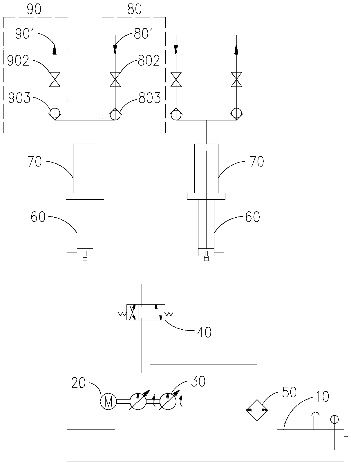
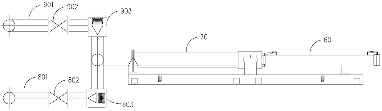
[0067] Example 1, such as Figure 5 As shown, a high-pressure slurry delivery pump system includes a power system and a hydraulic system, and the power system includes: a hydraulic oil tank 10, a main motor 20, a main oil pump 30, a hydraulic reversing valve 40, a cooler 50 and a main oil cylinder 60, The hydraulic system includes: delivery cylinder 70, feed subsystem 80 and discharge subsystem 90; wherein, feed subsystem 80 includes: feed pipe 801, feed pipe inspection valve 802 and feed cone valve 803, and the discharge subsystem 90 includes: discharge pipe 901, discharge maintenance valve 902 and discharge cone valve 903;

[0068] The main motor 20 is connected with the main oil pump 30, the main oil pump 30 is connected with the hydraulic oil tank 10, the hydraulic reversing valve 40 is respectively connected with the main oil pump 30, the cooler 50, the main oil cylinder 60a and the main oil cylinder 60a' through pipelines, and the main oil cylinder 60a is connected with ...

Embodiment 2

[0071] Example 2, such as Figure 6 As shown, a high-pressure slurry delivery pump system includes a power system and a hydraulic system, and the power system includes: a hydraulic oil tank 10, a main motor 20, a main oil pump 30, a hydraulic reversing valve 40, a cooler 50 and a main oil cylinder 60, The hydraulic system includes: delivery cylinder 70, feed subsystem 80 and discharge subsystem 90; wherein, feed subsystem 80 includes: feed pipe 801, feed pipe inspection valve 802 and feed cone valve 803, and the discharge subsystem 90 includes: discharge pipe 901, discharge maintenance valve 902 and discharge cone valve 903;

[0072] The main motor 20 is connected with the main oil pump 30, the main oil pump 30 is connected with the hydraulic oil tank 10, and the hydraulic reversing valve 40 is respectively connected with the main oil pump 30, the cooler 50, the main oil cylinder 60a, the main oil cylinder 60a', the main oil cylinder 60b and the main oil cylinder through pipel...


PUM


Abstract

The invention relates to fluid pumping equipment, in particular to a high-pressure slurry conveying pump system and method. The high-pressure slurry conveying pump system comprises a power system anda hydraulic system. The power system comprises a hydraulic oil tank, a main motor, a main oil pump, a hydraulic reversing valve, a cooler and main oil cylinders. The hydraulic system comprises conveying cylinders, a feeding subsystem and a discharging subsystem. The high-pressure slurry conveying method comprises the steps that firstly, the hydraulic oil tank, the main motor and the main oil pumpcontrol pistons in the main oil cylinders to do reciprocating motion through switching of the hydraulic reversing valve; secondly, the pistons in the main oil cylinders drive pistons in the conveyingcylinders to do reciprocating motion; and thirdly, when the pistons in the conveying cylinders move backwards, a feeding conic valve is opened, a discharging conic valve is closed, slurry is sucked infrom a feeding pipe, when the pistons in the conveying cylinders are pushed forwards, the feeding conic valve is closed, the discharging conic valve is opened, and the slurry is discharged from a discharging pipe. The high-pressure slurry conveying pump system and method have the advantages of being high in conveying efficiency, safe and reliable to use, simple in structure and flexible in mounting.

Description

technical field [0001] The invention relates to fluid pumping equipment, in particular to a high-pressure slurry delivery pump system and method. Background technique [0002] At present, the tailings long-distance conveying pumps often used in mine mining are as follows: [0003] Mud plunger pump, including motor, crankshaft linkage, plunger cylinder, suction valve, discharge valve, etc. The working principle is: the gear shaft driven by the motor meshes with the gear on the crankshaft, the crankshaft obtains a decelerated circular motion, and converts the rotational motion into the reciprocating motion of the plunger through the crankshaft linkage mechanism. Under the action of the reciprocating movement of the piston, the suction valve and the discharge valve in the sealed liquid cylinder are opened and closed regularly to achieve the purpose of continuous slurry delivery. [0004] Hydraulic diaphragm pump, including motor, crankshaft linkage, plunger cylinder, hydrauli...

Claims


Application Information

Patent Timeline
Patent Type & Authority Applications(China)
IPC IPC(8): F04B9/103F04B15/02F04B23/06F04B49/00F04B53/10
CPCF04B9/103F04B15/02F04B23/06F04B49/002F04B53/10
Inventor 张朝辉刘永红胡保华夏端雪
Owner 日昌升集团有限公司
Why Eureka
Try Eureka