Nozzle structure suitable for pulsation combustor vibration combustion and design method

A technology of pulsating combustion and oscillating combustion, which is applied in the direction of combustion methods, burners, gas fuel burners, etc., can solve the problems that the burner cannot work normally and stably, and achieve the goal of reducing manpower and material resources, development cycle, simple structure and low cost Effect

Active Publication Date: 2018-12-07
BEIHANG UNIV
View PDF7 Cites 4 Cited by
  • Summary
  • Abstract
  • Description
  • Claims
  • Application Information

AI Technical Summary

Problems solved by technology

Due to the complexity of the pulsation combustion mechanism, each component of the pulsation burner plays a vital role in the overall operation, and a deviation in the design of a certain component may cause the entire burner to fail to work normally and stably

Method used


Image

  • Nozzle structure suitable for pulsation combustor vibration combustion and design method
  • Nozzle structure suitable for pulsation combustor vibration combustion and design method
  • Nozzle structure suitable for pulsation combustor vibration combustion and design method

Examples


Embodiment Construction

[0040] In order to make the purpose, technical solutions and advantages of the present invention clearer, the implementation of the present invention will be further described in detail below in conjunction with the accompanying drawings.

[0041] In this embodiment, the nozzle structure design method of the present invention is used for the nozzle design of the pulse burner in the oil field, and the implementation process of the method is described in detail. The effectiveness of the invention is verified by comparing the experimental results of nozzles with different structures.

[0042] Below in conjunction with accompanying drawing, the present invention will be further described:

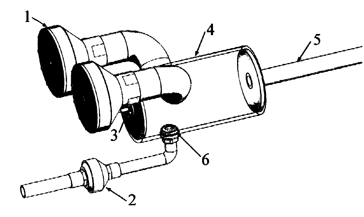
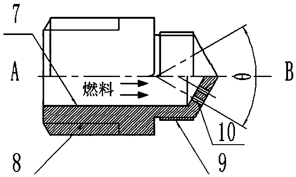
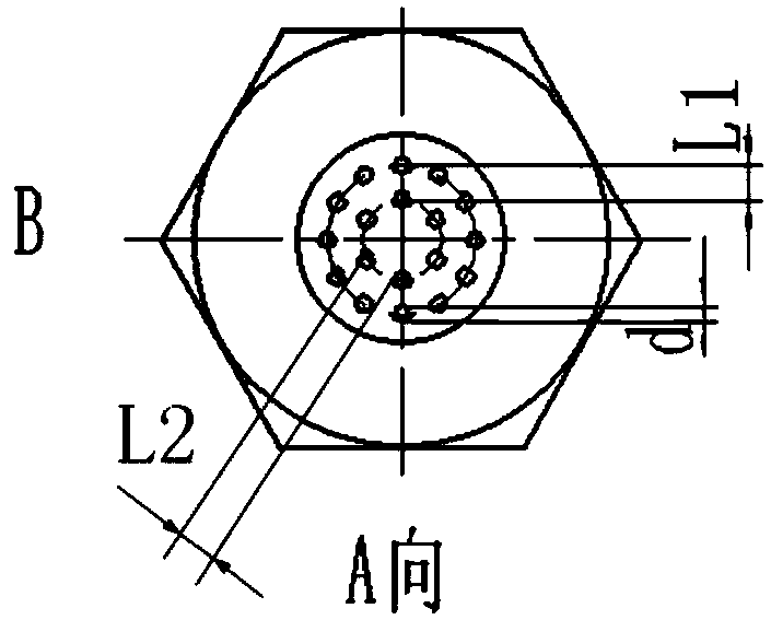
[0043] Such as figure 1 Shown is a schematic diagram of the arrangement and installation of the pulsation burner nozzle. An oilfield pulsation burner is used for heating crude oil or natural gas for export, and the fuel is oilfield associated gas. The pulse burner is composed of two air chec...


PUM


Abstract

The invention provides a nozzle structure suitable for pulsation combustor vibration combustion and a design method, a pulsation combustor can most properly conduct combustion and stably run, and thenozzle structure is simple, convenient to install and low in cost. Compared with a traditional design method, the workload of tests in design can be reduced, and manpower and material resources consumed by the tests and the development period are greatly reduced. The nozzle structure comprises a fuel channel (7), the bottom of the fuel channel (7) is provided with a thread (8) connected with a gasone-way valve, the top is provided with a thread (9) connected with a combustion chamber, the top of the fuel channel (7) is of a conical structure, fuel spraying holes (10) are evenly distributed inthe top face, and the two times of the included angle between the axis of the spraying holes (10) and the axis of the fuel channel (7) is the spray angle theta. The number of the spraying holes and the spraying hole distribution structure are determined according to the outlet area Ag of the nozzle structure.

Description

technical field [0001] The invention belongs to the technical field of pulsation combustion, and in particular relates to a nozzle structure and design method suitable for oscillating combustion of a pulsation burner. Background technique [0002] The pulse burner is a burner based on pulse combustion technology. During the combustion process, the parameters characterizing the process in the combustion zone, such as pressure, flow rate, temperature and heat release rate, change periodically with time. Compared with burners based on steady-state combustion, pulsating burners have high combustion intensity and combustion efficiency; excellent heat transfer characteristics and high thermal efficiency; low smoke pollutant emissions; self-breathing characteristics, no need to Blowing also does not need to use a chimney to exhaust smoke, which can greatly save fuel and structural materials. So far, pulsating combustion devices have been successfully applied in space or water heat...

Claims


Application Information

Patent Timeline
Patent Type & Authority Applications(China)
IPC IPC(8): F23D14/48
CPCF23D14/48F23D2900/14482
Inventor 杨立军李敬轩杜明龙覃粒子富庆飞
Owner BEIHANG UNIV
Why Eureka
Try Eureka