Waste liquid combustion treatment system

A treatment system and waste liquid technology, applied in the direction of combustion method, combustion type, incinerator, etc., can solve problems such as deterioration of temperature conditions, waste of secondary energy, fire hazards, etc., to eliminate safety hazards, good absorption effect, and low overall cost Effect

Active Publication Date: 2018-12-07
HENAN WANHE MACHINERY
View PDF6 Cites 2 Cited by
  • Summary
  • Abstract
  • Description
  • Claims
  • Application Information

AI Technical Summary

Problems solved by technology

If the liquid fuel discarded after the experiment is discharged directly, it will pollute the environment and bring fire hazards
Burning waste fuel in a combustion furnace will generate a large amount of heat in a short period of time. If the heat is released directly into the air, it will cause a waste of energy and cause a sharp rise in the temperature in the laboratory, resulting in a high temperature in the room. As the conditions deteriorate, it is necessary to further turn on the laboratory air conditioner to cool down, which leads to a waste of energy
[0003] At present, there is a lack of a combustion treatment system suitable for treating waste liquid fuels on the market

Method used


Image

  • Waste liquid combustion treatment system
  • Waste liquid combustion treatment system
  • Waste liquid combustion treatment system

Examples


Embodiment Construction

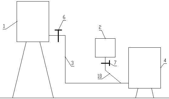
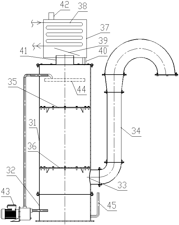
[0050] Such as Figure 1 to Figure 11 As shown, the waste liquid combustion treatment system of the present invention includes a waste liquid combustion device, a heat recovery heat exchanger and a tail gas treatment device.

[0051] Such as Figure 1 to Figure 6 As shown, the waste liquid combustion device includes a collection tank 1 for containing waste liquid fuel and a high-pressure gas source 2 for providing compressed air. The collection tank 1 is connected to a waste liquid combustion furnace through a waste liquid pipe 3; the flow of waste liquid The direction is the downstream direction;

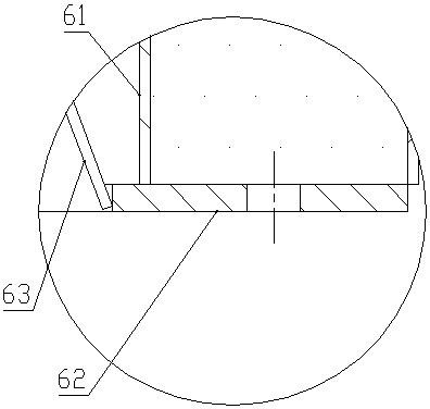
[0052] The waste liquid combustion furnace includes a furnace body 4 made of steel. The horizontal section of the furnace body 4 is circular. The inner wall of the furnace body 4 is provided with a refractory mud layer 5 so as to avoid direct heating of the furnace body 4 by high flame temperature and avoid excessive temperature of the furnace body 4. ; The lower end of the furna...


PUM


Abstract

The invention discloses a waste liquid combustion treatment system. The system comprises a waste liquid combustion device, a heat recovery heat exchanger and a tail gas treatment device; the waste liquid combustion device comprises a collecting tank and a high-pressure air source, the collecting tank is connected with a waste liquid combustion furnace through a waste liquid pipe; the waste liquidcombustion furnace comprises a furnace body, a refractory mud layer is arranged on the inner wall of the furnace body, the lower end of the furnace body is closed, and an opening is formed in the upper end of the furnace body; the high-pressure air source communicates with the waste liquid pipe through a high-pressure air pipe, and an igniter is arranged at an opening of one end, extending into the furnace body, of the waste liquid pipe; the heat recovery heat exchanger comprises a heat exchange barrel which is vertically arranged; and the tail gas treatment device comprises a tower body, a water tank is arranged at the bottom of the tower body, a tail gas inlet is formed in the side wall of the tower body arranged on the water tank, two layers of porous plates are arranged at intervals inthe portion, above the tail gas inlet, of the tower body, a filling material is arranged on each porous plate, and the top end of the tower body is connected with a condenser through a tail gas outlet pipe. According to the system, liquid fuel waste liquid generated in a laboratory can be sufficiently combusted, heat generated by combustion can be recycled, and harmful components in the tail gascan be fully absorbed.

Description

technical field [0001] The invention relates to the technical field of waste liquid treatment, in particular to the combustion, heat recovery and tail gas purification technologies of laboratory liquid fuels. Background technique [0002] The laboratory often uses flammable and explosive liquid fuels. The common flammable and explosive liquid fuels in the laboratory include: benzene, toluene, methanol, ethanol, petroleum ether and acetone, etc. If the liquid fuel discarded after the experiment is discharged directly, it will pollute the environment and bring fire hazards. Burning waste fuel in a combustion furnace will generate a large amount of heat in a short period of time. If the heat is released directly into the air, it will cause a waste of energy, and cause a sharp rise in the temperature in the laboratory, resulting in a high temperature in the room. As the conditions deteriorate, it is necessary to further turn on the laboratory air conditioner to cool down, which...

Claims


Application Information

Patent Timeline
Patent Type & Authority Applications(China)
IPC IPC(8): F23G7/04
CPCF23G7/04
Inventor 刘永生申哲民魏立波李学伟景红涛郭慧鸽戴强
Owner HENAN WANHE MACHINERY
Why Eureka
Try Eureka