
Afterburning air system for combined cycle heat recovery boiler

A technology of waste heat boiler and combined cycle, which is applied in the direction of combustion method, combustion control, and fuel supply adjustment, and can solve the problems that the fuel cannot be used for the supplementary combustion system of the waste heat boiler, gas and oil fuel cannot be fully combusted, and the loss of unburned is high. , to achieve the effect of improving burner performance, increasing combustion efficiency, and simple and reliable structure

Active Publication Date: 2018-12-07
HARBIN BOILER
View PDF12 Cites 0 Cited by
  • Summary
  • Abstract
  • Description
  • Claims
  • Application Information

AI Technical Summary

Problems solved by technology

However, due to the limitation of the oxygen concentration of gas turbine exhaust, some gas and oil fuels cannot be fully combusted by the afterburning burner, resulting in high unburned losses and low economic benefits, and even some fuels cannot be used for afterburning in waste heat boilers system

Method used


Image

  • Afterburning air system for combined cycle heat recovery boiler

Examples


Embodiment 1

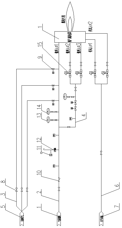
[0020] A post-combustion air system for a combined cycle waste heat boiler, which consists of: a post-combustion burner 1, and the post-combustion burner is arranged at the inlet flue section of the waste heat boiler or arranged between the heating surface according to the thermal calculation results of the system The position between the burner and the control cabinet, the afterburner has a group of fuel inlet ports, a group of air supply ports, compressed air ports, the fuel inlet port and the gas fuel main pipeline 2 connections, the gas fuel main pipeline is connected to a group of compressed air pipelines 3 and auxiliary gas pipelines 4, the compressed air pipeline is connected to the air compressor 5, and the air supply interface is connected to the air supply pipeline 6, The air supply pipeline is connected with the air blower 7 .

[0021] The nozzle of the supplementary combustion burner is triangular. In the project, through the flow field simulation analysis, the spe...

Embodiment 2

[0023] According to the supplementary combustion air system of the combined cycle waste heat boiler described in Embodiment 1, the shut-off valve 8 and the electric shut-off valve 9 are installed on the compressed air pipeline.

Embodiment 3

[0025] According to the supplementary combustion air system of the combined cycle waste heat boiler described in Embodiment 1, the gas fuel main pipeline is equipped with a shut-off valve, a check valve 10, a PCV valve 11, and an atmospheric discharge pipeline 12, and the atmospheric discharge pipeline is A PCV valve is installed, and a local pressure gauge 13 and a remote pressure gauge 14 are installed on the gas fuel main pipeline between the compressed air pipeline and the auxiliary air gas pipeline.


PUM


Abstract

The invention provides an afterburning air system for a combined cycle heat recovery boiler. Addition of an afterburning burner at an inlet of a heat recovery boiler is adopted as an effective means of improving the heat exchange efficiency of the heat recovery boiler and increasing generation load of a power station. However, because of limitations of oxygen concentration of smoke discharged froma combustion gas turbine, sufficient combustion cannot be conducted on certain gas and oil fuel through the afterburning burner. The afterburning air system for the combined cycle heat recovery boiler comprises an afterburning burner (1). The burner is connected with a control cabinet. The afterburning burner is provided with a set of fuel inlet interfaces, a set of air supply interfaces and a compressed air interface. The fuel inlet interfaces are connected with a gas fuel main pipeline (2). The gas fuel main pipeline is connected with a set of compressed air pipelines (3) and an auxiliary fuel gas pipeline (4). The compressed air pipelines are connected with an air compressor (5). The air supply interfaces are connected with an air supply pipeline (6). The air supply pipeline is connected with an air draught fan (7). The afterburning air system for the combined cycle heat recovery boiler is used in a novel air supply system of the afterburning burner of the combined cycle heat recovery boiler.

Description

Technical field: [0001] The invention relates to a supplementary combustion air system for a combined cycle waste heat boiler. Background technique: [0002] In recent years, the power industry has been developing rapidly. The gas-steam combined cycle power generation technology has developed a complete technical system since the early 20th century. It is a mature power generation technology with reliable technology, stable operation and a large user group. The market demand of combined cycle power plants at home and abroad is stable, and all enterprises are actively developing and improving combined cycle waste heat boiler technology. [0003] Adding a supplementary combustion burner at the inlet of the waste heat boiler is an effective means to improve the heat transfer efficiency of the waste heat boiler and increase the power generation load of the power station. However, due to the limitation of the oxygen concentration of gas turbine exhaust, some gas and oil fuels ca...

Claims


Application Information

Patent Timeline
Patent Type & Authority Applications(China)
IPC IPC(8): F23N1/02
CPCF23N1/025F23N2235/02F23N2235/12
Inventor 高新宇王瑀
Owner HARBIN BOILER
Learn More