Medium-voltage AC-DC dual-purpose high-power isolation switch

A technology of AC and DC dual-purpose and isolating switches, which is applied in the direction of electric switches, air switch parts, high-voltage air circuit breakers, etc., and can solve the problems of operators not being able to see the correct position of the moving knife assembly, practicability and operability Hidden dangers, cumbersome overall structure of the isolating switch, etc., to achieve good electrical conductivity, ensure brazing welding quality, and good arc erosion resistance

Pending Publication Date: 2018-12-07
金晓亮 +2
View PDF0 Cites 2 Cited by
  • Summary
  • Abstract
  • Description
  • Claims
  • Application Information

AI Technical Summary

Problems solved by technology

[0006] 1. The upper contact of the isolating switch knife is made of silver contacts, which are pressed to both ends of the input, and the output copper terminals are usually made of thin plate springs. The pressure is weak and insufficient, resulting in increased contact resistance and isolation. The temperature of the switch will increase during use
[0007] 2. Due to manufacturing and material reasons of the moving knife assembly and the input and output copper terminals of the isolating switch, the current density in use is as high as 2.5-3A / mm 2 , will further increase its temperature when used in a closed electrical cabinet
This will easily cause the heat of the switch and form a vicious circle: As a result, the user needs to use two fans to carry out forced air cooling in the electrical cabinet, and some conductive parts of the disconnecting switch that have failed will all turn black. It can be seen that the temperature of the disconnecting switch that has failed has often exceeded 400°C
[0008] 3. The base of the isolating switch is made of bent 4mm thick steel plate, and its shape and position error is more than 0.2mm, so that all the parts installed on the base can only be adjusted randomly one by one, and the product assembly size is different, interchangeable poor sex
[0009] 4. The overall mechanism of the isolating switch is cumbersome, and the operator often cannot see the correct position of the moving knife assembly, and there are hidden dangers in practicability and operability

Method used


Image

  • Medium-voltage AC-DC dual-purpose high-power isolation switch
  • Medium-voltage AC-DC dual-purpose high-power isolation switch
  • Medium-voltage AC-DC dual-purpose high-power isolation switch

Examples


Embodiment Construction

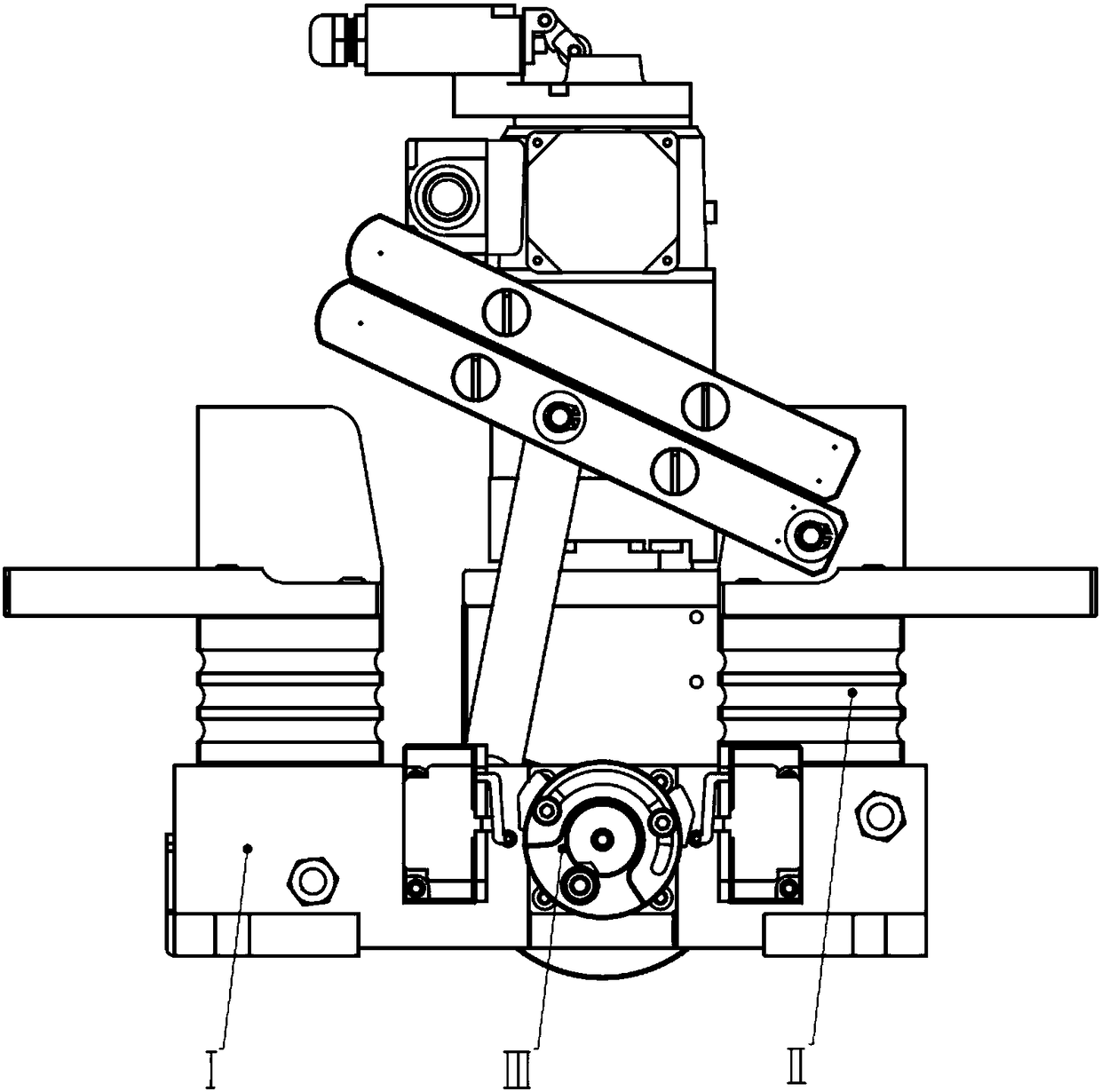
[0039] Such as figure 1 , The isolating switch in the present invention is mainly composed of three major parts: the base and the transmission part I, the conductive and insulating part II and the drive and control part III. The isolating switch and its components will be described in detail below in conjunction with the accompanying drawings:

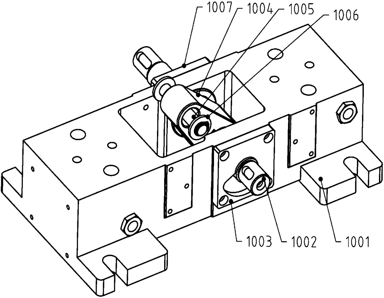
[0040] Frame and Transmission PartsⅠ

[0041] Such as figure 2 , on the left and right sides of the aluminum base 1001 are respectively provided with a left end cover 1003 that can brake the moving knife assembly at the end position, and a right end cover 1007 that can adjust the axial play of the main shaft. There is a main shaft 1002 and an intermediate swing rod 1004 connected to the main shaft. A swing rod shaft 1005 is arranged on the end of the middle swing rod 1004. The swing rod shaft 1005 is connected with an insulating pull rod 2006. Between the insulating pull rod 2006 and the swing rod shaft 1005 For rotating hinge conn...


PUM


Abstract

The invention discloses a medium-voltage AC-DC dual-purpose high-power isolation switch, which comprises a base and conductive and insulating components arranged on the base, wherein the conductive and insulating components include an insulator and a conductive component arranged on the insulator, the conductive component includes an input terminal, an output terminal and a movable knife switch assembly with one end being in articulated connection with the output terminal which are arranged on the insulator, the movable knife switch assembly includes multiple copper bars, two ends of each copper bar are respectively provided with contacts, and the contacts adopt beryllium bronze with the hardness being HRC42-44. The isolation switch has the characteristics of stable performance, low cost,long service life and the like, and can meet great demands of traction power supply systems such as metros, light rails and cloud rails in urban rail transit in China and high-power three-phase four-wire AC power grids.

Description

technical field [0001] The invention relates to a high-power isolating switch capable of turning on / off the power supply in a high-power transmission and distribution system, used in medium voltage (3.6kV), high current (5.3kA), AC and DC dual-purpose; mainly It is applied in the power transmission and distribution system of urban rail transit traction power supply substation. Through the output of the high-power isolating switch, it provides the electric energy required for the operation of urban subways, light rails, cloud rails, trams, and trolleybuses. [0002] It is widely used in the medium-voltage three-phase four-wire grid, as well as in metallurgy, machinery, chemical industry, automobile, shipbuilding, hydropower, wind power, atomic energy industries, and all fields involving medium voltage and high current. Background technique [0003] my country started late in the field of urban rail transit, and its technical level in some fields lagged behind that of develop...

Claims


Application Information

Patent Timeline
Patent Type & Authority Applications(China)
IPC IPC(8): H01H31/02H01H21/54
CPCH01H31/023H01H21/54H01H31/026
Inventor 杨维雄
Owner 金晓亮
Why Eureka
Try Eureka