
PMSM torque ripple inhibition method in stator current vector orientation

A technology of stator current vector and torque ripple, which is applied in torque ripple control, electronically commutated motor control, motor control, etc., can solve the large pulse of permanent magnet synchronous motors, the inability of rotor error-free tracking, and the limitation of permanent magnet synchronous motors Application and other problems, to achieve the effect of torque ripple suppression and torque ripple suppression

Active Publication Date: 2018-12-07
NORTH CHINA ELECTRIC POWER UNIV (BAODING)
View PDF2 Cites 7 Cited by
  • Summary
  • Abstract
  • Description
  • Claims
  • Application Information

AI Technical Summary

Problems solved by technology

However, due to the non-ideal design of the motor structure, the distortion of the air gap magnetic field and the nonlinearity of the inverter, the torque of the permanent magnet synchronous motor has a large pulsation, which limits the application of the permanent magnet synchronous motor in high-precision applications.
The conventional PI controller cannot track the rotor speed without error, and can only suppress the torque ripple caused by the inherent characteristics of the inverter switching device and the dead time, and has no effect on the torque ripple caused by other reasons. Obvious inhibitory effect

Method used


Image

  • PMSM torque ripple inhibition method in stator current vector orientation
  • PMSM torque ripple inhibition method in stator current vector orientation
  • PMSM torque ripple inhibition method in stator current vector orientation

Examples


Embodiment Construction

[0033] The present invention is realized by the following technical solutions:

[0034] 1. Dynamic modeling of PMSM under stator current vector orientation

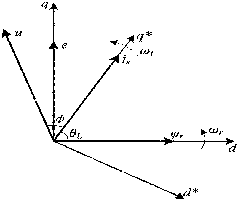
[0035] In order to study the current vector i in PMSM s The characteristics of the introduction of synchronous rotating coordinate system d * q * o such as figure 1 , where d * and q * are the real axis and imaginary axis respectively, and the dq axis is the actual rotation axis of the rotor. q * Axis direction and current vector i s direction remains the same. q * The angle between the axis and the d-axis is θ L , ψ r is the excitation space vector of the permanent magnet.

[0036] in d * q * In the o coordinate system, the stator voltage equation can be expressed as:

[0037]

[0038]

[0039] where: R s is the stator resistance; and respectively d * axis and q * shaft stator current; and respectively d * axis and q * shaft stator voltage; and respectively d* axis and q * The stato...


PUM


Abstract

The present invention provides a PMSM (Permanent Magnet Synchronous Motor) torque ripple inhibition method in stator current vector orientation. The control method comprises the steps of: establishinga dynamic mathematical model of a PMSM in the stator current vector orientation according to the actual operation parameters of the PMSM; and based on an electromagnetic torque equation in a PMSM magnetic co-energy model, establishing an optimal stator harmonic current constraint condition when the minimization of the torque ripple is ensured, and utilizing a backstepping control principle to establish a harmonic controller and a closed-loop I / f controller in the stator current vector orientation (for short, closed-loop I / f controller). In order to accurately obtain speed signals, the presentinvention designs a PMSM total-range speed identification method based on the least squares algorithm. The test result shows that the optimized motor torque ripple is effectively inhibited, parameters under the control can be rapidly converged and can achieve a stable value; and moreover, for low, middle and high rotation speeds, the PMSM torque ripple inhibition method in stator current vector orientation can perform accurate tracking and identification to achieve PMSM full-speed tracking.

Description

technical field [0001] The invention relates to a control method of a permanent magnet synchronous motor, belonging to the technical field of motors. Background technique [0002] With the rapid development of power electronics technology, new motor control theory and rare earth permanent magnet materials, permanent magnet synchronous motors (permanent magnet synchronous motor, PMSM) can be rapidly popularized and applied. Permanent magnet synchronous motors have the advantages of simple structure, high power density, high efficiency, and low loss, and are widely used in various industrial drive fields, such as electric vehicles, CNC machine tools, and aerospace engineering. However, due to the non-ideal design of the motor structure, the distortion of the air-gap magnetic field, and the nonlinearity of the inverter, the torque of the permanent magnet synchronous motor has a large pulsation, which limits the application of the permanent magnet synchronous motor in high-preci...

Claims


Application Information

Patent Timeline
IPC IPC(8): H02P6/10H02P21/05H02P21/22
CPCH02P6/10H02P21/05H02P21/22H02P2205/01Y02E40/40
Inventor 余洋从乐瑶谢仁杰田夏卢健斌
Owner NORTH CHINA ELECTRIC POWER UNIV (BAODING)
Learn More