Pulse thickened-oil exploiting device and method for exploiting thickened oil by pulses

A technology of pulse wave and heavy oil, which is applied in heavy oil exploitation engineering, pulse wave exploitation heavy oil device and pulse wave exploitation heavy oil field, which can solve the problems such as difficult maintenance, difficult development, difficult to guarantee recovery rate, etc.

Pending Publication Date: 2018-12-11
BC P INC CHINA NAT PETROLEUM CORP +1
View PDF19 Cites 2 Cited by
  • Summary
  • Abstract
  • Description
  • Claims
  • Application Information

AI Technical Summary

Problems solved by technology

[0003] The present invention provides a device for exploiting heavy oil with pulse wave and a method for exploiting heavy oil with pulse wave, which overcomes the deficiencies of the above-mentioned prior art, and can effectively solve the problems of large investment, difficulty in later maintenance, and problems in the previous heavy oil mining method. This problem is difficult to develop and the recovery rate is difficult to guarantee

Method used


Image

  • Pulse thickened-oil exploiting device and method for exploiting thickened oil by pulses
  • Pulse thickened-oil exploiting device and method for exploiting thickened oil by pulses
  • Pulse thickened-oil exploiting device and method for exploiting thickened oil by pulses

Examples


Embodiment 1

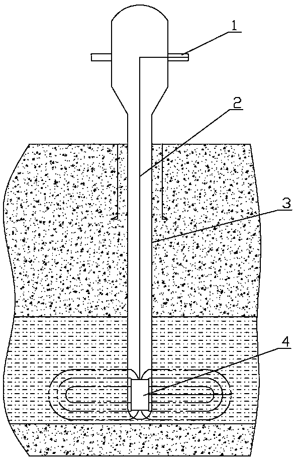
[0024] Embodiment 1, as attached figure 1 As shown, the pulse wave recovery heavy oil device includes a wellhead device 1, a transmission device 2, an oil layer string 3 and a flow conversion device 4; a wellhead device 1 capable of providing high-frequency pulse wave fluid and a transmission device 2 Located in the oil layer pipe string 3, the flow conversion device 4 is arranged at the bottom of the well, the outlet end of the wellhead device 1 is fixedly installed and communicated with the inlet end of the transmission device 2, and the outlet end of the transmission device 2 is connected to the inlet end of the flow conversion device 4 They are fixedly installed together and communicated with each other, and the diverter hole 9 for transmitting the pulse fluid to the oil layer is arranged on the flow diverter device 4 . The wellhead device 1 can generate high-frequency pulse wave fluid, and the high-frequency pulse wave fluid is transported to the flow-changing device 4 th...

Embodiment 2

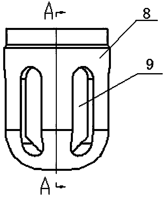
[0025] Embodiment 2, as the optimization of embodiment 1, as attached figure 1 , 2 , 3, and 4, the flow conversion device 4 includes a shunt short and more than two Helmholtz self-resonating cavity shorts, and more than two Helmholtz self-resonating cavity shorts are installed together up and down in sequence to form Helmholtz natural cavity short-circuit group, the lower end of the bottom Helmholtz natural cavity short-connector in the Helmholtz natural-resonant cavity short-circuit group is fixedly installed with the upper end of the shunt short-circuit; 3 can be a combination of casing strings and screen strings, the upper rock layer is a casing string, and the lower oil zone is a screen string; the flow conversion device 4 converts the high-frequency pulse wave fluid provided by the wellhead device 1 Low-frequency pulse fluid of heavy oil layers with different viscosities, and the low-frequency fluid pulse wave is transmitted to the oil layer through shunt short circuit. ...

Embodiment 3

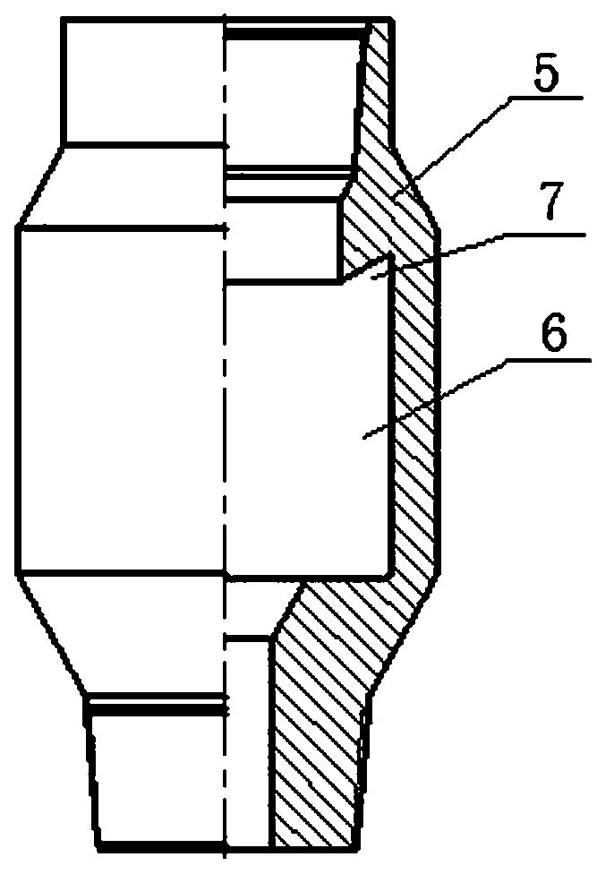
[0027] Embodiment 3, as the optimization of embodiment 2, as attached figure 2 As shown, the Helmholtz natural vibration cavity short circuit includes a tubular body 5, a natural vibration cavity 6 with an inner diameter larger than the inner diameter of the body 5 is arranged on the inner wall of the body 5, and a dovetail groove 7 is arranged on the upper wall of the natural vibration cavity 6 . Due to its unique internal structure, the Helmholtz natural cavity short circuit in the variable flow device 4 can transform the high-frequency pulsed fluid provided by the wellhead device 1 into a low-frequency pulsed fluid suitable for heavy oil reservoirs with different viscosities.


PUM


Abstract

The invention relates to the technical field of thickened-oil exploitation, relating to a pulse thickened-oil exploiting device and a method for exploiting thickened oil by pulses. The pulse thickened-oil exploiting device and the method for exploiting thickened oil by pulses are suitable for thickened-oil exploitation projects with oil field high viscosity and poor mobility. The device comprisesa well mouth device, a transmission device, an oil layer pipe string and a convertor device. The outside of the well mouth is equipped with a well moth device capable of providing a high frequency pulse fluid. The device and the method are primarily used for the thickened-oil exploitation projects with oil field high viscosity and poor mobility. The traditional thickened oil exploitation idea is changed. The oil well exploitation structure is simplified. Miniature cracks are formed in a stratum by pulses. Therefore, seepage rate of rocks in the stratum is increased. Rocking dissolving is avoided due to impact of pulses upon thicken oil. The fluid property is greatly improved. Meanwhile, combined with biological and chemical flooding, density and viscosity are reduced. The recovery difficulty is lowered. Pulses form miniature cracks in the stratum, which further increases seepage rate of rocks in the stratum. Fluidity of thickened oil is effectively changed so that oil well recovery efficiency is improved.

Description

technical field [0001] The invention relates to the technical field of heavy oil mining, and relates to a pulse wave heavy oil mining device and a pulse wave heavy oil mining method, which are suitable for heavy oil mining projects with high viscosity and poor fluidity in oil fields. Background technique [0002] Heavy oil reservoirs have the characteristics of shallow burial, thin oil layer, dense oil quality, scattered distribution, low ratio of pure to total thickness, and serious reservoir heterogeneity, so it is difficult to be effectively exploited by conventional mining methods. At present, the technical means of mining heavy oil generally include: steam huff and puff, cold sand production, fracturing to aid production, etc. However, through years of mining, it has been found that the previous mining methods not only require too much investment, but also are difficult to maintain and redevelop later, and the recovery rates are also difficult to guarantee. Contents o...

Claims


Application Information

Patent Timeline
Patent Type & Authority Applications(China)
IPC IPC(8): E21B43/16E21B43/22
CPCE21B43/16
Inventor 郭新超李勇龙张武涛颜斌
Owner BC P INC CHINA NAT PETROLEUM CORP
Why Eureka
Try Eureka