
Optical fiber distributed monitoring system and method

A fiber optic distributed and monitoring system technology, applied in the direction of optical instrument testing, measuring devices, optical devices, etc., can solve the problems of system dynamic range limitation, complexity, low accuracy of demodulation data, etc.

Active Publication Date: 2018-12-11
LASER RES INST OF SHANDONG ACAD OF SCI
View PDF8 Cites 10 Cited by
  • Summary
  • Abstract
  • Description
  • Claims
  • Application Information

AI Technical Summary

Problems solved by technology

[0003] The PGC scheme needs to increase the carrier, and it needs to collect the interference light and the modulation wave at the same time, that is, it needs to demodulate two signals at the same time, so the frequency and amplitude of the carrier need to be strictly quantified to meet the requirements of the demodulation accuracy of the system. The dynamic range of the system is limited by the carrier frequency
3×3 coupler demodulation requires simultaneous acquisition of 3 signals, which leads to a larger amount of data and complicates the system, because the 3×3 coupler demodulation principle is based on an included angle of 120°, but the actual production of 3×3 couplers does not It is not exactly 120°, so the included angle of the 3×3 coupler will also affect the demodulation accuracy
[0004] To sum up, the process of obtaining demodulation data in the prior art is relatively complicated, and there are many factors affecting the accuracy, resulting in low accuracy of the obtained demodulation data

Method used


Image

  • Optical fiber distributed monitoring system and method
  • Optical fiber distributed monitoring system and method
  • Optical fiber distributed monitoring system and method

Examples


Embodiment Construction

[0031] In order to make the purpose, technical solutions and advantages of the embodiments of the present invention clearer, the technical solutions in the embodiments of the present invention will be clearly and completely described below in conjunction with the drawings in the embodiments of the present invention. Obviously, the described embodiments It is a part of embodiments of the present invention, but not all embodiments. The components of the embodiments of the invention generally described and illustrated in the figures herein may be arranged and designed in a variety of different configurations. Accordingly, the following detailed description of the embodiments of the invention provided in the accompanying drawings is not intended to limit the scope of the claimed invention, but merely represents selected embodiments of the invention. Based on the embodiments of the present invention, all other embodiments obtained by persons of ordinary skill in the art without cre...


PUM


Abstract

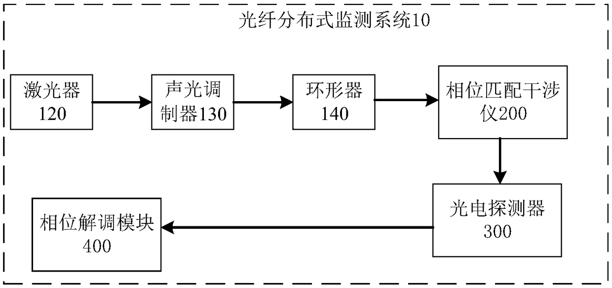
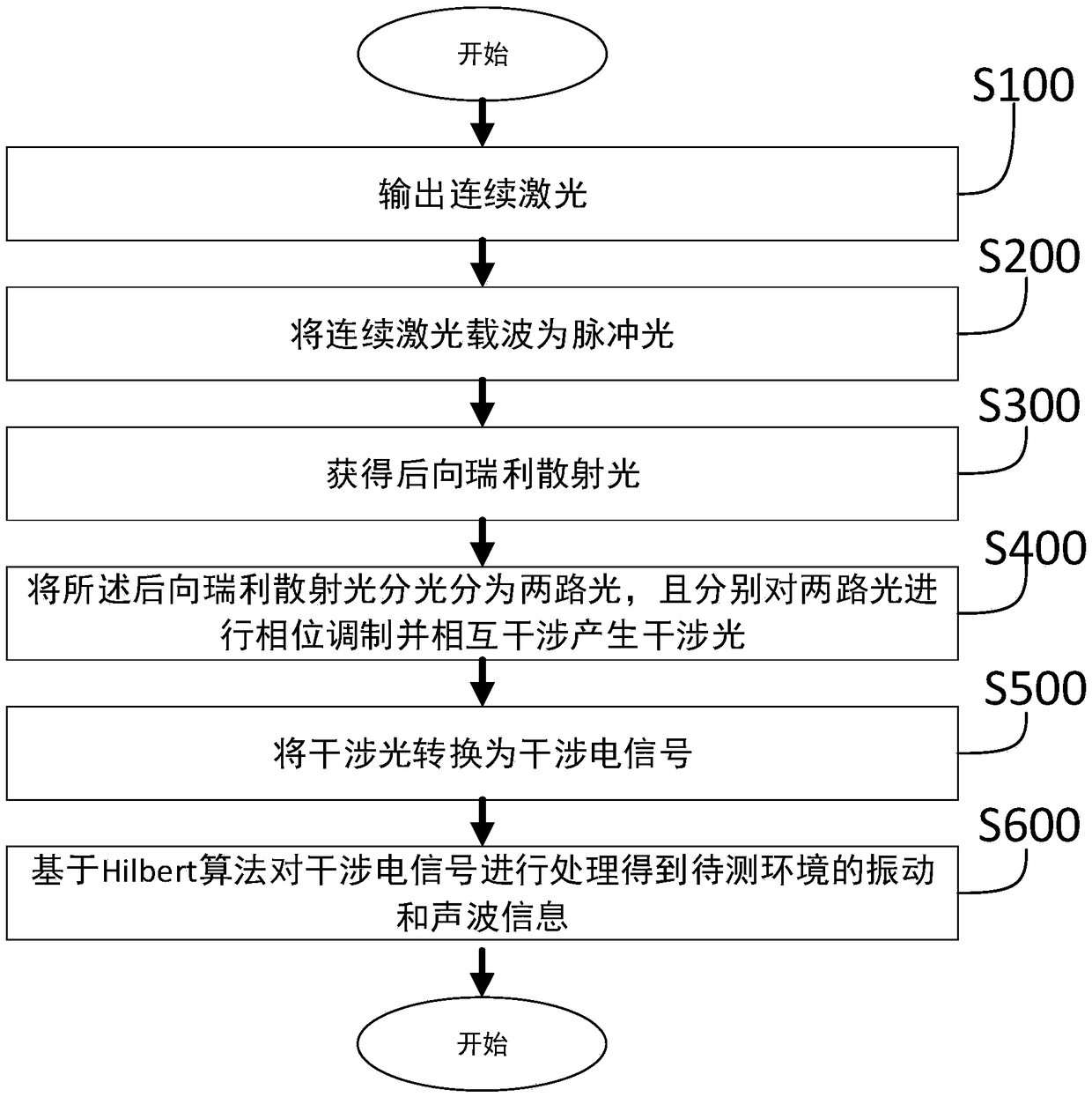
The embodiment of the invention provides an optical fiber distributed monitoring system and method, and relates to the field of optical fiber sensing. The system includes a laser, an acousto-optic modulator, a phase matching interferometer, a photoelectric detector, and a phase demodulation module. The backward Rayleigh scattered light, containing the parameter information, of a sensing optical fiber enters the phase matching interferometer and then enters the two arms of the phase matching interferometer. The phases of the light of two arms of the phase matching interferometer are modulated through a first modulation waveform and a second modulation waveform, and then the light of two arms of the phase matching interferometer interferes with each other to generate interference light. Thephotoelectric detector converts an optical signal into an electric signal, and the phase demodulation module processes the electric signal based on the Hilbert algorithm to obtain the parameter changecondition of a to-be-tested environment. Since there is no need of the collection of the modulation waveform when the Hilbert algorithm is used for processing, and the amplitude difference between afirst modulated wave and a second modulated wave is greater than or equal to an amplitude difference threshold capable of enabling the phase difference of the two arms of the phase matching interferometer to be 2*Pi, the processing can be performed.

Description

technical field [0001] The invention relates to the field of optical fiber sensing, in particular to an optical fiber distributed monitoring system and method. Background technique [0002] Optical fiber distributed sensing technology can continuously measure the external physical parameters distributed along the optical fiber geometric path. It is widely used in intelligent bridges, highways, important buildings, gas pipeline monitoring and other fields. Optical fiber distributed monitoring mainly includes two distributed monitoring systems based on intensity demodulation and phase demodulation. The distributed monitoring system of intensity demodulation can only demodulate the back Rayleigh scattered light intensity change information within a unit pulse. The scope of application limited, and the distributed monitoring system of phase demodulation can demodulate the phase information of the back Rayleigh scattered light interference light in a unit pulse, which has a wide...

Claims


Application Information

Patent Timeline
Patent Type & Authority Applications(China)
IPC IPC(8): G01D5/353G01D21/02
CPCG01D5/35306G01D21/02G01D5/35361G01H9/004G01M11/331G01M11/334G01B9/02041G01B9/02056
Inventor 尚盈王晨王昌倪家升李常曹冰赵文安黄胜刘杨刘小会王英英
Owner LASER RES INST OF SHANDONG ACAD OF SCI
Learn More