
Three-dimensional scanning laser radar based on MEMS micromirrors

A 3D scanning and lidar technology, applied in the field of 3D scanning lidar, can solve the problems of small plane size of MEMS micromirrors, difficult to achieve long-distance detection, and inability to control large-size light spots, etc., to achieve reliable quality, low power consumption, easy to use. The effect of mass production

Active Publication Date: 2018-12-11
SHENZHEN KYLE OPTICS TECH CO LTD
View PDF5 Cites 12 Cited by
  • Summary
  • Abstract
  • Description
  • Claims
  • Application Information

AI Technical Summary

Problems solved by technology

The patent also ignores the size of the MEMS micromirror. At present, the plane size of a single MEMS micromirror is small, and it cannot control a large-sized spot, and it is difficult to achieve long-distance detection. This is also the MEMS micromirror application that must be optimized in the lidar industry. key design

Method used


Image

  • Three-dimensional scanning laser radar based on MEMS micromirrors
  • Three-dimensional scanning laser radar based on MEMS micromirrors
  • Three-dimensional scanning laser radar based on MEMS micromirrors

Examples


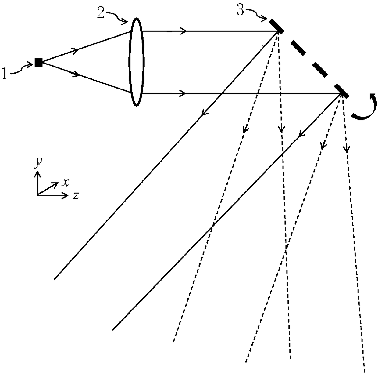
Embodiment 1

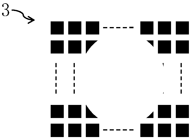
[0027] In order to solve the above problems, this embodiment proposes a two-dimensional MEMS small mirror array design scheme, such as figure 2 Shown. The MEMS micro-mirror is decomposed into multiple small micro-mirror units. Each small micro-mirror unit can be rotated at a large angle without taking up too much space in the thickness direction. It can be manufactured based on the existing semiconductor technology and is easy to mass produce. A small micro-mirror unit forms a large-size MEMS micro-mirror array 3, which can realize long-distance detection for large-size light spots, solves the application limitation of MEMS micro-mirrors in large-size light spot lidars, and helps realize long-distance detection of lidar .

[0028] Such as figure 1 As shown, this embodiment provides a three-dimensional scanning lidar based on MEMS micromirrors, including a transmitting laser 1, a collimating optical element 2, a MEMS micromirror array 3, and a detector; the detection laser signal...

Embodiment 2

[0036] This implementation proposes a two-dimensional MEMS micro-mirror array design plan, which decomposes the MEMS micro-mirror into multiple small micro-mirror units. Each small micro-mirror unit can achieve large-angle rotation and does not occupy much space in the thickness direction. It can be manufactured based on the existing semiconductor technology and is easy to mass-produce. Multiple small micro-mirror units form a MEMS micro-mirror array 3.

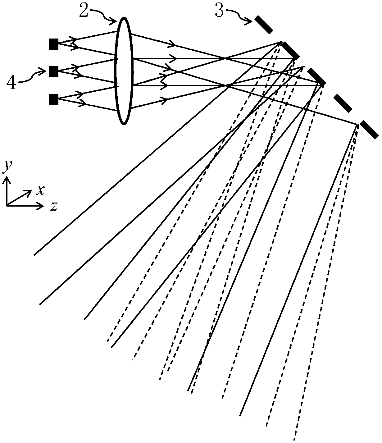
[0037] image 3 It is a schematic diagram of the optical path principle of Embodiment 2 of the MEMS micromirror-based three-dimensional scanning lidar of the present invention. Such as image 3 As shown, this embodiment provides a three-dimensional scanning lidar based on MEMS micromirrors, including a transmitting laser array 4, a collimating optical element 2, a MEMS micromirror array 3, and a detector; the detection laser signal emitted by the transmitting laser passes through the collimating optics The element (the collimati...


PUM


Abstract

The invention belongs to the technical field of laser radars, and discloses a three-dimensional scanning laser radar based on MEMS (Micro-Electro Mechanical System) micromirrors. The three-dimensionalscanning laser radar based on MEMS micromirrors includes an emitting laser, a collimated optical element, an MEMS micromirror array and a detector, wherein a detection laser signal emitted by the emitting laser is collimated by the collimated optical element to the MEMS micromirror array, and then is emitted to a detection target through the MEMS micromirror array; the detection laser signal reflected by the detection target is received by the detector; and the MEMS micromirror array includes a plurality of small micromirror units which are arranged in a two-dimensional array, and all the small micromirror units are rotatable in the three-dimensional direction. The design of replacing a single small-sized MEMS micromirror with a large-sized two-dimensional MEMS micromirror array can solvethe application limitation of the MEMS micromirrors in a large-size spot laser radar, thus being conductive to implementation of long-distance detection of the laser radar.

Description

Technical field [0001] The invention belongs to the technical field of laser radar, and specifically relates to a three-dimensional scanning laser radar based on a MEMS micromirror. Background technique [0002] Lidar is a device that scans the surrounding space and obtains spatial parameters by emitting laser signals. It is widely used in industries such as geographic surveying and mapping, environmental detection, industrial scanning or unmanned driving. At present, the beam scanning method of lidar is mainly motor scanning, but the scanning motor has obvious defects such as large size, high power consumption, complex control circuits and algorithms, which limit the development of lidar towards miniaturization, integration and low power consumption. The speed of development in the same direction also restricts the further popularization and application of lidar. [0003] The Micro-Electro Mechanical System (MEMS) micromirror is based on a mature semiconductor processing technolo...

Claims


Application Information

Patent Timeline
Patent Type & Authority Applications(China)
IPC IPC(8): G01S7/481
CPCG01S7/4817
Inventor 张石李亚锋鲁佶
Owner SHENZHEN KYLE OPTICS TECH CO LTD
Learn More