
An interferometric lithography system with controllable period and direction

A technology of interference lithography and cycle, applied in micro-lithography exposure equipment, optics, optomechanical equipment, etc., can solve the problems of long process cycle, expensive equipment, low production efficiency, etc., and achieve flexible and easy adjustment of the device, time reduction, low cost effect

Inactive Publication Date: 2018-12-11
INST OF OPTICS & ELECTRONICS - CHINESE ACAD OF SCI
View PDF5 Cites 5 Cited by
  • Summary
  • Abstract
  • Description
  • Claims
  • Application Information

AI Technical Summary

Problems solved by technology

Electron beam exposure + ion beam etching is usually used to prepare integrated polarization gratings, but the problems of expensive equipment, long process cycle, low production efficiency, and inability to realize large-area preparation severely limit the development and application of polarization gratings.

Method used


Image

  • An interferometric lithography system with controllable period and direction
  • An interferometric lithography system with controllable period and direction
  • An interferometric lithography system with controllable period and direction

Examples


Embodiment Construction

[0021] The invention proposes a method for preparing a grating with a 325nm wavelength laser, through the flexible control of the optical path, the purpose of flexibly changing the interference angle is achieved, thereby realizing the preparation of the grating with a controllable period and direction. In order to better understand the technical solution of the present invention, a further detailed description will be made below in conjunction with the accompanying drawings.

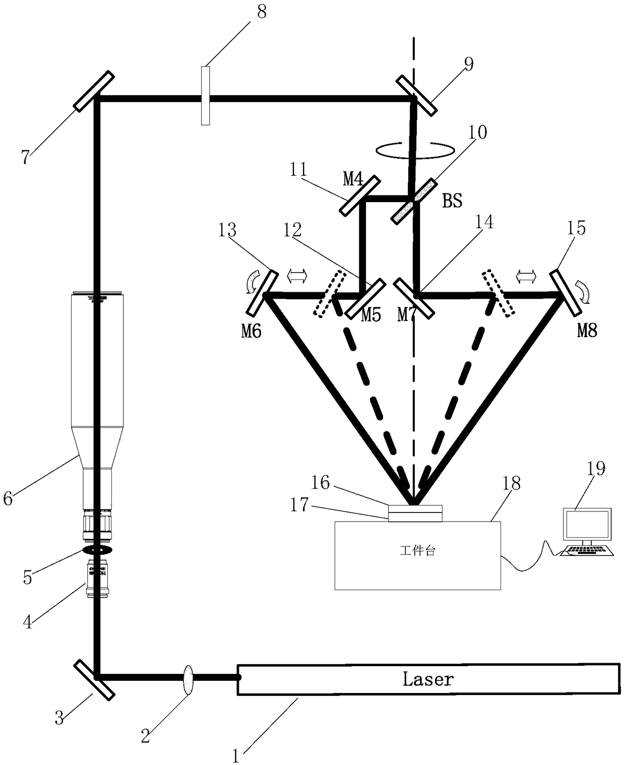
[0022] see figure 1 , is a schematic diagram of the optical path of an interference lithography system with controllable period and direction implemented in the present invention. Its system mainly includes laser 1, shutter 2, first mirror 3, ultraviolet focusing objective lens 4, pinhole 5, collimating mirror 6, second mirror 7, aperture 8, third mirror 9, beam splitter 10 , the fourth reflector 11, the fifth reflector 12, the sixth reflector 13, the seventh reflector 14, the eighth reflector 15, the m...


PUM


Abstract

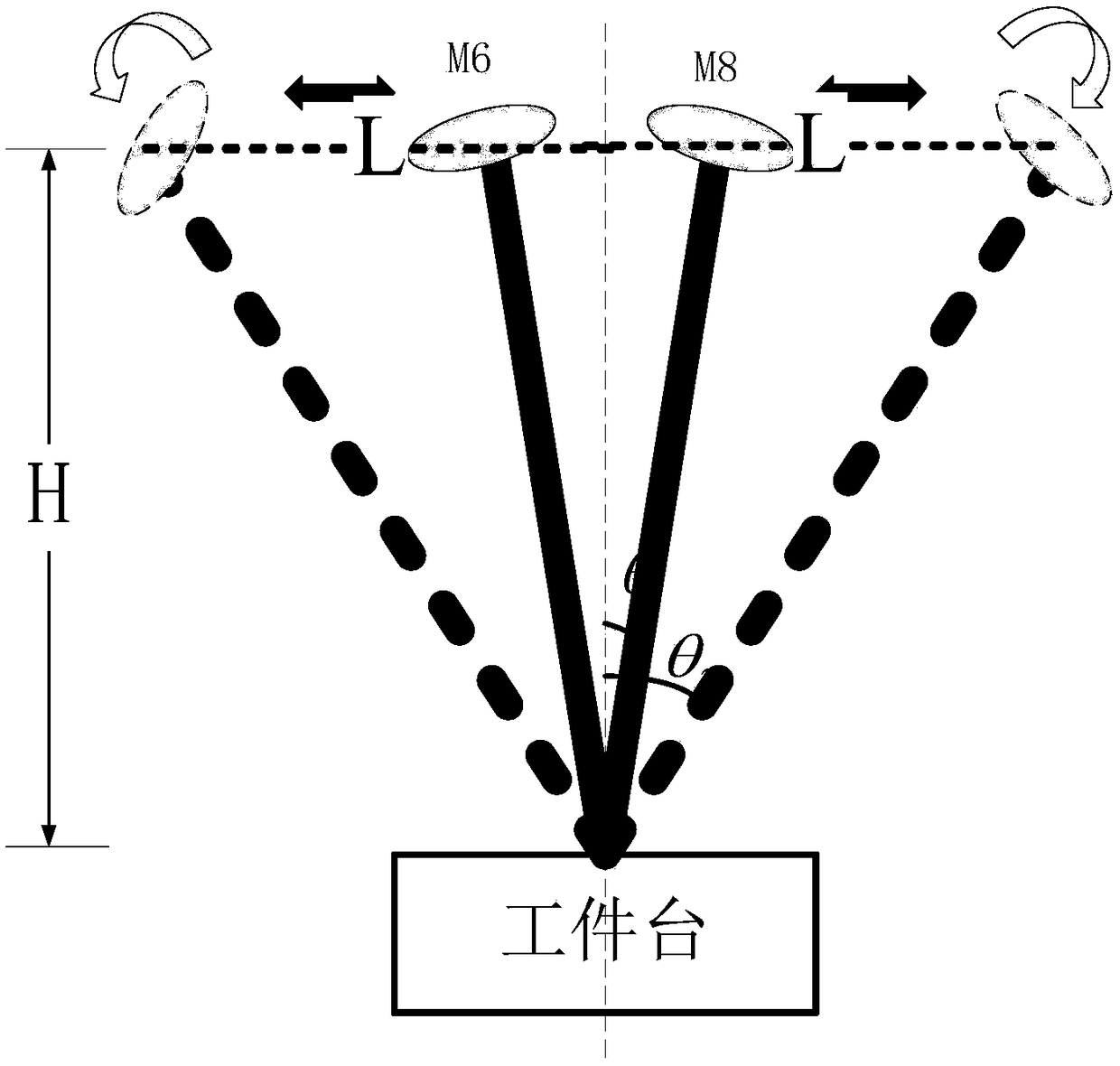
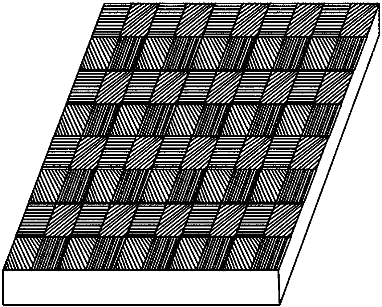
The invention discloses an interference lithography system with controllable period and direction, wherein the light of the light source is reflected by a first mirror and collimated into parallel beams through a beam expansion filter module, the beams are reflected twice by a second mirror and a third mirror and propagated vertically downward, and then are divided into two coherent beams with equal amplitude by a beam splitter mirror. The reflected beam is reflected three times by the fourth, fifth and sixth mirrors, and the transmitted beam is reflected twice by the seventh and eighth mirrors, and finally converges and interferes on the substrate. A mask plate locate above that substrate is closely attached to the substrate, and the substrate is place on the workpiece table. By moving the positions of the sixth and eighth mirrors laterally and adjusting the angles of the sixth and eighth mirrors, interference of different angles is achieved without changing the height of the substrate in the z direction. The computer control system realizes the horizontal movement and rotation of the sixth and eighth mirrors as well as the precise control of the worktable. The pixel-level array polarization grating with different periods can be prepared by the invention.

Description

technical field [0001] The invention belongs to the technical field of photolithography for semiconductor micro-nano processing, and in particular relates to an interference photolithography system with controllable period and direction. The system can be used to quickly realize the preparation of grating lines with a period of 100 nanometers. Background technique [0002] The interference phenomenon of light is the performance of the wave nature of light, and many optical measuring instruments use the interference principle of light. After the light interferes, the energy of the light is redistributed in space, resulting in the generation of interference fringes. [0003] In recent years, technologies such as projection exposure technology and electron beam have repeatedly broken the record of the smallest size. The development of micro-nano processing technology enables us to manufacture devices with smaller size, higher precision and more complex structure. Electron beam...

Claims


Application Information

Patent Timeline
Patent Type & Authority Applications(China)
IPC IPC(8): G03F7/20
CPCG03F7/70025G03F7/7015G03F7/70175G03F7/70408
Inventor 彭伏平严伟杨帆李凡星田鹏赵立新胡松
Owner INST OF OPTICS & ELECTRONICS - CHINESE ACAD OF SCI
Learn More