A Verification Method for Structural Bonding of Composite Parts

A composite material and calibration method technology, which is applied in the calibration field of composite material parts structural bonding, can solve the problems of high calibration cost and difficult operation, and achieves reduction of manufacturing cost, guarantee of accuracy, and reduction of calibration. cost effect

Active Publication Date: 2020-12-01
CHENGDU AIRCRAFT INDUSTRY GROUP
View PDF3 Cites 0 Cited by
  • Summary
  • Abstract
  • Description
  • Claims
  • Application Information

AI Technical Summary

Problems solved by technology

[0004] The purpose of the present invention is to provide a method for verifying the structural bonding of composite material parts, so as to solve the problems of difficult operation and high cost of verification during the verification of the existing composite material structure bonding, and to make the verification operation easier , reduce manufacturing costs

Method used


Image

  • A Verification Method for Structural Bonding of Composite Parts
  • A Verification Method for Structural Bonding of Composite Parts
  • A Verification Method for Structural Bonding of Composite Parts

Examples


Embodiment 1

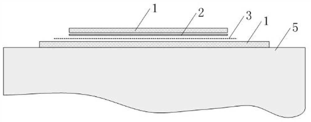
[0034] A verification method for structural bonding of composite parts, such as figure 1 As shown, it mainly includes the following steps:

[0035] Step S101: Use a rheometer to test the adhesive film 2 to obtain the in-situ calibration parameters of the adhesive film 2; and determine the calibration pressure according to the pressure of the adhesive film 2 when bonding;

[0036] Step S102: Lay the adhesive film 2 flat on the adhesive surface of the surface of the one-sided adhesive structural member 1, the adhesive film 2 is the same shape as the adhesive surface; then lay the adhesive film 2 on the surface One layer of isolation film 3, the area of ​​the isolation film 3 is greater than the area of ​​the adhesive film 2;

[0037] Step S103: Position and assemble the structural part 1 and seal the vacuum bag, and perform verification according to the verification parameters of temperature, time, and pressure in step S101; after the verification is completed, remove the vacuu...

Embodiment 2

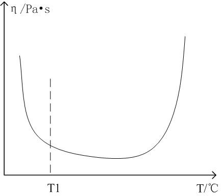
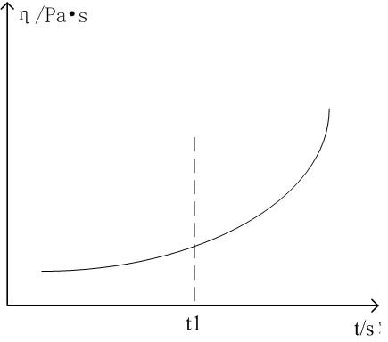
[0041] This embodiment is optimized on the basis of embodiment 1, such as figure 2 , image 3As shown, in the step S101, first use a rheometer to test the viscosity of the adhesive film 2 for bonding by using a rheometer to obtain the initial softening temperature point of the adhesive film 2, and give a calibration temperature point T1; secondly, use a rheometer to test the constant temperature viscosity of the adhesive film 2 for bonding, and then obtain the available calibration time t1; determine the calibration pressure P1 according to the pressure selected during bonding. In said S103, the verification is performed in an autoclave or an oven according to the temperature T1, time t1, and pressure P1. The adhesive bonding film 2 after verification in step S103 is not removed from the structural member 1, and is directly used for bonding the structural member 1 after the compensation is completed.

[0042] In the present invention, the glue film for glue bonding is direc...

Embodiment 3

[0045] This embodiment is optimized on the basis of Embodiment 1 or 2. In the step S102 , a margin of 20-40 mm is reserved for the isolation film 3 relative to the periphery of the adhesive film 2 . The margin left on the isolation film 3 can ensure that the film will not be contaminated on the structural part 1 on the other side during the verification process, which has better practicability.

[0046] In the present invention, the glue film for glue bonding is directly laid on the glue joint area for verification. After the verification is completed, the glue film is not removed, and the glue film is directly compensated according to the pressure state of the glue film, thus avoiding the traditional verification. In the method, the compensation area is determined on the structural part 1 according to the verification film, and the compensation area is more accurate, which reduces the difficulty of the verification operation, and the adhesive film is directly used for bonding ...


PUM


Abstract

The invention discloses a method for validating structural bonding of composite parts. The method comprises the following steps: performing positioning assembly on structural parts and encapsulating avacuum bag, and validating according to measured validation parameters of temperature, time and pressure; removing the vacuum bag after validation completion, taking out the assembly, measuring the bonding film, and determining the compensation thickness of the bonding film and the number of layers of the used bonding film according to the stress state and area of the bonding film; removing a release film on the surface of the bonding film, and directly compensating by adopting the bonding film. According to the method disclosed by the invention, the bonding film is directly pasted in the bonding area for validation, the bonding film is not removed after validation completion, and bonding film compensation is directly performed on the bonding film according to the stress state of the bonding film, so that the condition that the compensation area is determined by contrasting the validation film on the structural parts in the traditional validation method is avoided, the compensation area is accurate, and the validation operating difficulty is reduced. Moreover, the bonding film completes validation to be directly used for bonding, and the validation cost is effectively reduced.

Description

technical field [0001] The invention belongs to the technical field of composite material processing and molding, and in particular relates to a verification method for structural bonding of composite material parts. Background technique [0002] At present, the integrated structural design is gradually becoming a major design concept of modern or future aircraft composite material structure design. The integrated design refers to the design of several parts as an integrated part, reducing the number of parts, the mechanical assembly requirements of parts and the assembly connection. Parts, and then realize the weight reduction of the structural design of the aircraft, and because of the characteristics of the simultaneous molding of the material structure of the composite material, the degree of integrated design of the parts is also getting higher and higher. [0003] At present, the integral molding technology of composite materials mainly adopts structural bonding proces...

Claims


Application Information

Patent Timeline
Patent Type & Authority Patents(China)
IPC IPC(8): B29C70/54
CPCB29C70/54
Inventor 徐伟伟程勇马开维文友谊李博
Owner CHENGDU AIRCRAFT INDUSTRY GROUP
Why Eureka
Try Eureka